


Transistor Servo-Drive TV6.2
24
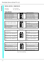
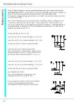
The current limiting can be adjusted internally by means of the po-
tentiometers P6 (I
max1
) and P5 (I
max 2
) from 0 and 200% type current (rated cur -
rent). In this case the switches S6:K2 and S6:K3 must be closed (ON).
For external current limiting adjustments or control the switches S6:K2 and S6:K3
must be open (OFF).
The current limiting can be switched from 0 to 200% by using a voltage of 0 to
+10V across the input X1:16c (X1:9) for the current limit 1 and across X1:14c
(X1:10) for current limit 2. For adjusting by means of external potentiometers or
voltage dividers a voltage of +10V is available across terminal X1:28c (X1:3)
against the GND X1:20c (X1:7).
Output X1:28c (X1:3) +10 Volt
Input X1:16c (X1:9) current limiting I1, 0 to +10V
Input X1:14c (X1:10) current limiting I2, 0 to +10V
Output X1:20c (X1:7) device ground GND
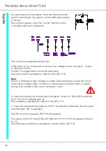
Switches S6:K2 and S6:K3 closed (ON).
The current limit I
1
is adjusted by means of the
potentiometer P-I
comm.val.1
, the current limit I
2
by means of the potentiometer P-I
comm.val.2
.
Input X1:16c (X1:9) current limiting I
1
, 0 to +10V
Input X1:14c (X1:10) current limiting I
2
, 0 to +10V
Output X1:20c (X1:7) device ground GND
Input resistance 50 kΩ
The current limiting is controlled by the
voltages across X1:16c and X1:14c .
For an external control current of 0 to 20mA
for the current limiting, the external
load resistors of 500 Ω must be connected.
Summary of Contents for TV 6.2
Page 12: ...Transistor Servo Drive TV 6 2 12 ...
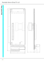
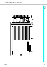
Page 13: ...TV6 2 13 3 Mechanical Installation ...
Page 14: ...Transistor Servo Drive TV 6 2 14 ...
Page 15: ...TV6 2 15 3 Mechanical Installation ...
Page 17: ...TV6 2 17 4 Adjustments Anschluss Kompaktgerät Anschluss Mehrachskombination ...
Page 38: ...Transistor Servo Drive TV6 2 38 ...
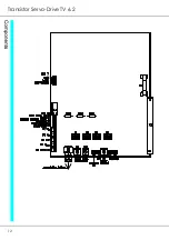
Page 39: ...TV6 2 39 8 Circuit Diagrams ...
Page 40: ...Transistor Servo Drive TV6 2 40 ...
Page 41: ...TV6 2 41 8 Circuit Diagrams ...


