39
749.082 | Z02 | 2015-02-03
EN
5 Installation
Notice
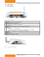
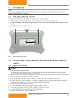
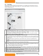
Please note the MAC address before installation. This is on the rear side of the IFA router and is re-
quired for registration (
②
in Fig. 7).
5.1 Installing the IFA router
The device can be fastened to a flat mounting surface (wall, ceiling):
1. Drill 2 holes in the mounting surface, at a clearance of 131 mm (see
①
in Fig. 7).
2. Screw a suitable screw into each hole, leaving 5 mm of the screw protruding (use dowels if neces-
sary).
3. Hang the IFA router on the screws.
131 mm
1
2
Fig. 7: Rear side of the IFA router
5.2 Connect the solar controller and USB flash drive to the IFA
router
5.2.1 Type A controller
Danger
Risk of death by electrocution!
Disconnect the controller from the mains power before opening. Make sure that the mains
power cannot be unintentionally reconnected.
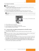
1. Disconnect the controller from the mains power.
2. Remove the terminal cover of the controller; see the controller operating instructions.
3. Connect the S232 interface cable to the correct terminals on the controller, observing the colour
coding of the conductors; see the controller operating instructions.
4. Fit the terminal cover of the controller.
5. Connect the RS232 interface cable to the RS232 USB converter.
6. Insert the USB plug of the RS232 USB converter into the USB hub.
7. Connect the USB hub to the USB port of the IFA router.
8. Plug the USB flash drive into the USB hub.

