


45
As a policy of continual improvement, STAUFF reserves the right to alter the specification without prior notice.
201.031
Date of Issue: 06 November 2018
Use the software to configure any CAN-bus specific parameters required by your CAN-bus
network, for example configure a CAN-bus message ID and baud rate
Figure 6.29
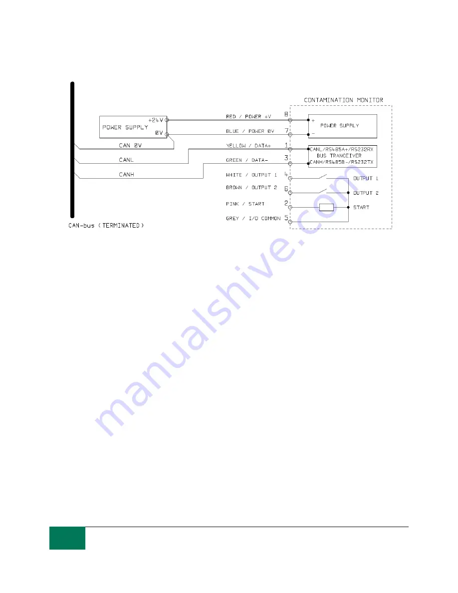
Connect the LPM to your CAN-bus network and provide a 24VDC power supply, as per figure
6.29.
The LPM automatically emits the test result message after each set test interval.
Configure your CAN-bus controller to listen for the messages configured above.
The LPM requires a DC power supply and the two CAN-bus signals CANL and CANH, as shown
in Figure 1. The numbers shown are the pin numbers of the circular connector that plugs into the
LPM.
CAN-bus requires the network to be terminated at each end. This must be done externally to the
LPM.
The CAN-bus signals CANL and CANH are referred to the system 0V supply. These should stay
within the common mode range allowed by the ISO-11898-4 CAN-bus standard relative to the
LPM 0V connection. This range is -2V to +7V. This can be normally be ensured by connecting
together the LPM 0V and the 0V of the CAN-
bus controller. The “CAN 0V” wire shown indicates
this link. (Not needed if both CAN-bus controller and LPM are connected to a vehicle chassis or
otherwise “Earthed”.)
There are other wires available for switched alarm and start signals (optional). These are
documented separately in section 6.1.2.
6.4.2.2 Configuration
6.4.2.2.1 Use PC Software for Configuration
The free LASPAC-View software package is needed in order to initially configure the LPM. Once
configured, the unit can be left connected to the CAN-bus network.
The LPM was designed to be as flexible as possible. There are large number of options for setting
operating modes, test result formats, alarm settings, downloading stored data etc.