


29
As a policy of continual improvement, STAUFF reserves the right to alter the specification without prior notice.
201.031
Date of Issue: 06 November 2018
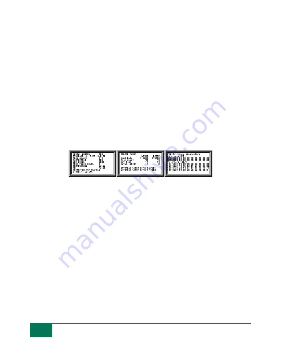
6.2.2.2.2 Diagnostics Display
Press ◄ or ► to show the diagnostics displays (used when diagnosing problems) shown in figure 6.15.
Then switch between the diagnostics screens using the ▲ and ▼ buttons.
Completion shows a number from 0 to 1000, indicating the test progress.
FLOW ml/min provides an approximate indication of flow rate, updated after each test.
NOTE: This is not a calibrated flow meter and is for indicative purposes only.
This can be helpful when installing the unit or checking operation, to ensure that the flow rate is within
the limits of the unit. The other items are mainly of use to assist in support when reporting problems.
The STATUS line shows the current state of the unit. Any errors such as LOW FLOW will also appear
here (corresponding to the front panel LED fault codes).
The second screen shows diagnostics relating to Modbus serial communications traffic. External Comms
Errors are those between a connected PC and the LPM. Internal Comms Errors are internal to the unit,
showing communications between the LPM keyboard/display circuit board and the sensor itself.
The third screen shows diagnostics related to CAN bus communications. For more details refer to the
separate LPM CAN bus manual.
General
Modbus
CAN Bus
Figure 6.15 Diagnostics Screens
6.2.3 LPM removal and Product Maintenance
When removing the LPM from the system ensure the system pressure is shut off from the LPM.
Blockages
If a suspected blockage occurs then flush system fluid in the reverse direction of the LPM.
If this doesn’t solve the problem then try using Iso-Propyl Alcohol or Petroleum Ether, flushing in
the standard and reverse flow direction.
If this doesn’t solve the issue then send to Stauff for investigation.
6.3 LPM Control
The LPM can be controlled using the remote control facility included in the LASPAC-View software
package, installed on a computer. Alternatively customers can use their own computer software.
Since the LPM includes a built-in data logging memory, operators can make use of the remote control
facility in one of two ways:
− Direct Online Operation
The LPM is permanently connected to a computer while tests are carried out. The operator can set
parameters, type a label and initiate the test. They can then monitor the progress of each test. Each test
result is displayed and downloaded into the test database as it is completed.
− Disconnected Operation