


19
As a policy of continual improvement, STAUFF reserves the right to alter the specification without prior notice.
201.031
Date of Issue: 06 November 2018
6.1.2.3 Machine Connector - Serial Interface
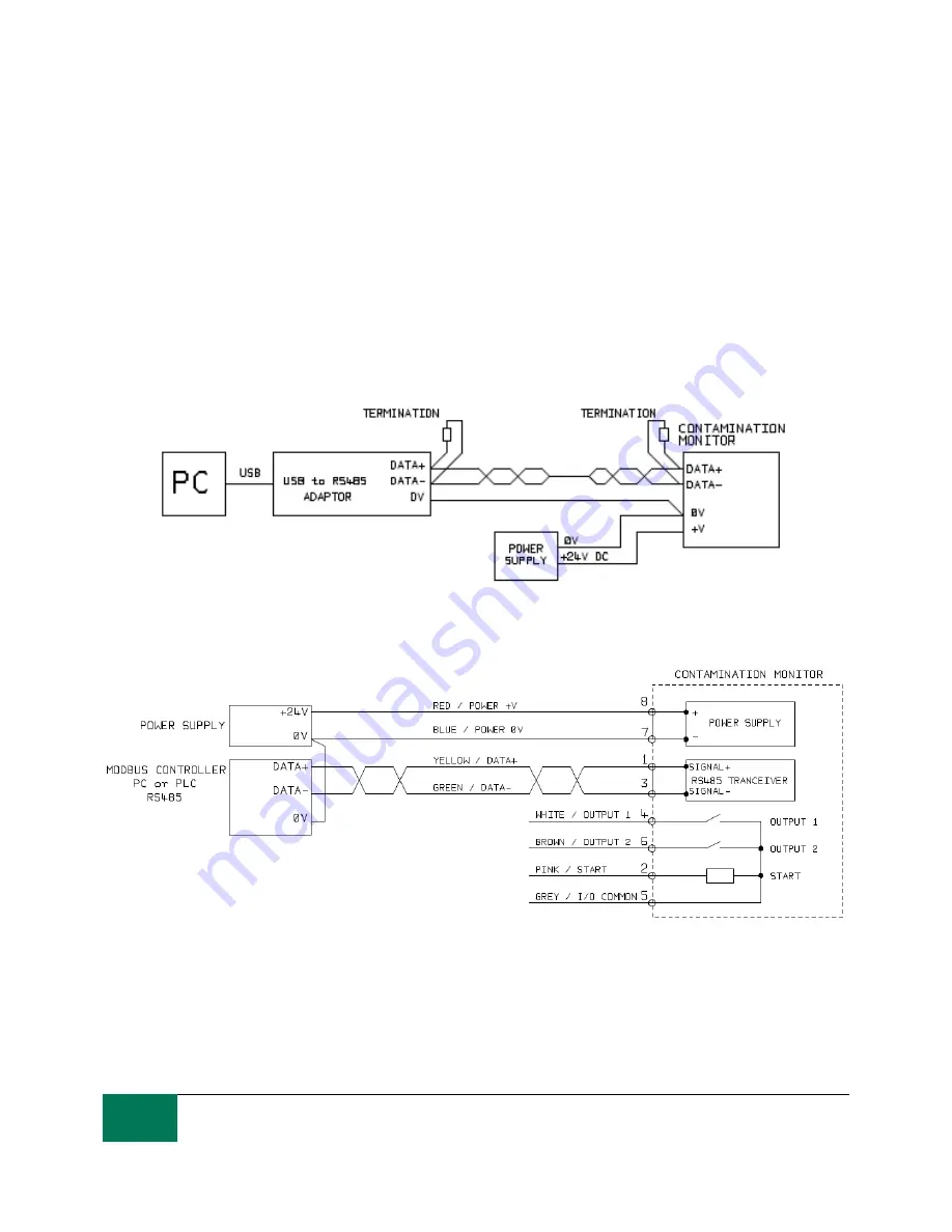
An RS485 or CANbus interface can optionally be connected to pins 1 and 3 (yellow and green). This can
be a PLC running customer software, or a PC with a RS485 adaptor running the supplied LASPAC-View
software. To provide a reference the RS485 0V connection should also be linked to the LPM 0V (as
shown on figure 6.3).
The standard LPM control protocol is Modbus RTU. Modbus is a freely available open standard for
industrial control. Adapters are available to interface to other industrial control busses. The standard
LASPAC-View software from Stauff itself uses Modbus to communicate with the LPM, but it is also
possible for customers to implement their own controllers (section Modbus).
The CANbus protocol can also be used, see separate LPM-CANbus manual.
Figure 6.3a PC Control Example
Figure 6.3b Modbus Controller Example
Figure 6.3a shows a single LPM linked to a PC, using a USB-RS485 adaptor. Figure 6.3b shows a
slightly different method. 100 Ohm termination resistors should be fitted as shown for long cables, for
example over 10m. Twisted pair wiring should be used for any length over 2m.