– 50 –
APPENDIX
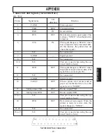
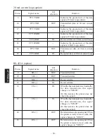
20 mA current loop (option)
Pin no.
Signal name
I/O
Function
direction
9
TTY TXDR
—
Indicates the ground side of the data
signal of 20 mA loop current.
10
TTY TXD
OUT
Transmitted data of 20 mA current
loop.
17
TTY TXDR
—
Indicates the ground side of the data
signal of 20 mA loop current.
18
TTY RXDR
—
Indicates the ground side of the data
signal of 20 mA loop current.
19
TTY RXD
IN
Received data of 20 mA current loop.
23
TTY RXDR
—
Indicates the ground side of the data
signal at 20mA loop current.
24
TTY TXD
OUT
Transmission data of 20 mA current
loop.
25
TTY RXD
IN
Reception data of 20 mA current loop.
RS-422A (option)
Pin no.
Signal name
I/O
Function
direction
9
SD (+)
OUT
Transmitted data
10
SD (–)
OUT
Transmitted data
17
RD (+)
IN
Received data
18
RD (–)
IN
Received data
19
CS (+)
IN
When the host computer is set to standby
for data transmission, this signal
changes to “SPACE”.
(In this instance, the printer does not
check the signal.)
23
CS (–)
IN
When the host computer is set to standby
for data transmission, this signal
changes to “SPACE”.
(In this instance, the printer does not
check the signal.)
24
RS (+)
OUT
Data transmission request signal. When
the printer is ready to receive data, this
signal changes to “SPACE”.
25
RS (–)
OUT
Data transmission request signal. When
the printer is ready to receive data, this
signal changes to “SPACE”.
APPENDIX
Summary of Contents for 347F
Page 14: ......
Page 26: ......
Page 38: ......
Page 50: ......
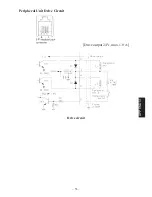
Page 55: ... 53 APPENDIX Peripheral Unit Drive Circuit Drive output 24V max 1 0 A Drive circuit ...
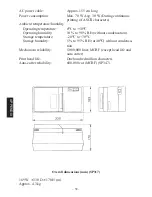
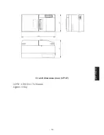
Page 61: ... 59 APPENDIX Overall dimensions mm SP347 169 W 330 D 176 H mm Approx 4 6 kg ...
Page 62: ...MEMO P 1996 01 P 1996 03 ...


