– 8 –
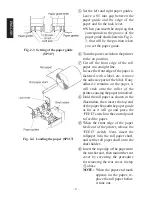
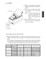
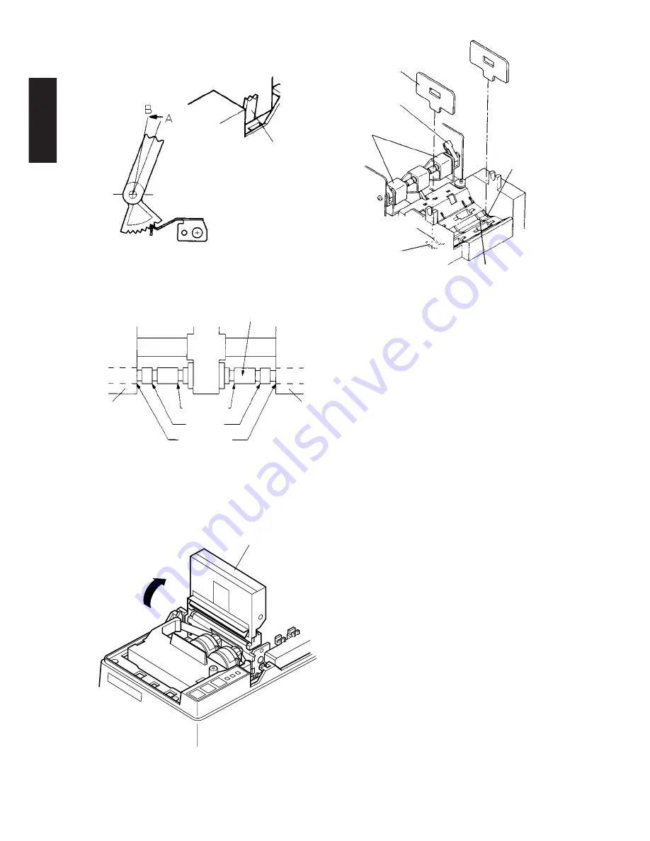
A: One Sheet of paper
(standard position)
B: Copy paper
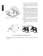
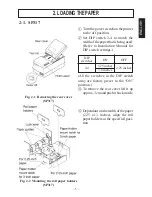
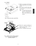
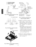
Fig. 2-6 Position of the adjust lever
(SP347)
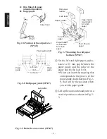
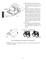
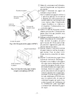
Fig. 2-8 Roll paper guide (SP347)
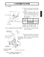
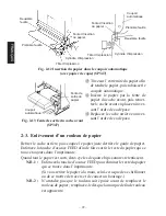
Fig. 2-9 Raise the auto cutter (SP347)
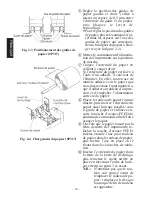
Fig. 2-7 Mounting the roll paper
holders (SP347)
5
Set the left and right paper guides.
Leave a 0.5 mm gap between the
paper guide and the edge of the
paper and fix the lock lever.
•
When you insert the stop ring that
corresponds to the groove of the
paper guide shaft shown in Fig. 2-
8, that will be the position when
you set the paper guide.
6
Lift up the auto cutter and put it in a
vertical position, as shown in Fig. 2-
9.
Auto cutter
ENGLISH
Adjust lever
Roll paper
holders
Lock lever
Paper guides
For 2.25-inch
paper
Paper holder
mount notch
for 3-inch
paper
Paper holder
mount notch
for 3-inch
paper
For 2.25-inch
paper
Paper guide shaft
Paper
guide
3 inch
2.25 inch
3.35 inch
Paper
guide
Summary of Contents for 347F
Page 14: ......
Page 26: ......
Page 38: ......
Page 50: ......
Page 55: ... 53 APPENDIX Peripheral Unit Drive Circuit Drive output 24V max 1 0 A Drive circuit ...
Page 61: ... 59 APPENDIX Overall dimensions mm SP347 169 W 330 D 176 H mm Approx 4 6 kg ...
Page 62: ...MEMO P 1996 01 P 1996 03 ...


