


Theta Controller
Programming
9
2.5.3
Menu Tree
A menu tree [
1
] appears beside related menu items.
2.5.4
Tabs
Tabs [
1
] appear at the top when multiple menu selections exist.
To navigate between tabs, use the left/right arrows. The active
tab is white; inactive tabs are grey.
2.5.5
Character Scrollbar
This scrollbar enables adding: a-z, A-Z, 0-9, space, _, -, &, *, $, #, @, !, and a
period (language and/or field determines character availability). The up arrow [
1
]
and down arrow [
3
] direct scrolling with the active character [
2
] displayed
between. Use the Theta Controller’s up/down arrows to scroll through character
choices. The left arrow backspaces. The right arrow moves one position to the right
to input next character. Push toggle button or OK menu button to accept entry.
The following screens contain the character scrollbar option: Job (Name), Step
(Name), System Name (General), and System (Users).
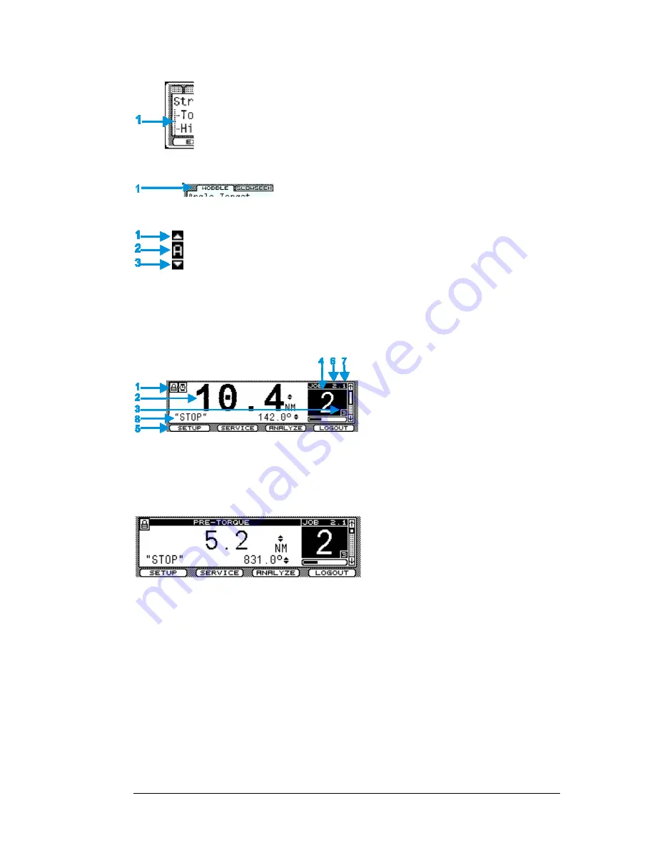
2.5.6
Run Display
Icons identify events [
1
] (see list below).
When a tool is connected, the last torque
and angle readings (and units) display [
2
].
Up/down arrows next to the torque or
angle value indicate the last fastening
cycle NOK status (exceeded
▲
or did not
achieve
▼
torque or angle limits).
Identifies the active Job [
6
] and active Task [
7
]. Identifies Target bolt count [
3
] and Accumulated
bolt count [
4
] for the active Job. The side scroll bar indicates events are available in the Event
Log. Press the down arrow to view the events. The number of fastening cycle attempts indicator is
below the bolt count box. The run screen displays unless other programming functions [
5
] are in
use. A Shutoff code is also displayed when applicable [
8
].
The run display changes to indicate the
step in which the tool stopped (providing it
did not stop during the audit step).
The display background color in normal operation is white. After an OK fastening cycle, the
display background color changes to green for two seconds, then reverts back to white for the next
cycle. After a NOK fastening cycle, the display background color changes to red for two seconds,
then reverts back to white for the next cycle. The display background color turns red in the event
of a fault; see section 2.6 Faults.
Shutoff Codes on the display indicate why a tightening cycle terminated prior to completion.
Shutoff Code
Description
TIME
Tightening time exceeds programmed Cycle Abort time value
STOP
Spindle stopped by either the operator or other device
125%
Spindle stopped due to torque achieving greater than 125% torque limit for the spindle
FAULT
Precedes a fault described in section
2.6 Faults
STALL
Spindle in stall status


