TDM
Universal Time Delay Module
INSTALLATION INSTRUCTIONS
8701 Castle Park Drive
Indianapolis, Indiana 46256
Telephone: (800) 842-2545/(317) 842-2545
www.mssedco.com
Page 1
(82A044) TDMv0605
Section 1
General Description
The TDM is a multipurpose timing module that can be
used for a variety of applications. Its unique design and
open architecture allows the TDM to be used in any
application that requires timing control of up to two
outputs with up to four inputs. Common applications
include: simple time delay, vestibule door sequencing
(only one device required) and electric lock/automatic
door operator sequencing.
The four inputs on the TDM allow sequencing or
independent operation of the two outputs. Input 1 will
sequence Outputs 1 then 2. Input 2 will sequence
Outputs 2 then 1. Input 3 will operate Output 1
independently. Input 4 will operate Output 2
independently.
Both outputs on the TDM are fully programmable for "on
time" duration as well as the delay time between the two
outputs from 0 to 99 seconds.
CAUTION:
Devices to be controlled by the TDM
must be low voltage (12-24V) but can be
inductive loads. Surge suppressors are standard
on the TDM.
WET/DRY CONTACT OPTION:
The TDM has the option to supply power to Relay Output
1 contacts. This is known as having a "Wet" contact
instead of the conventional "Dry" contact closure. To use
output 1 as a "Wet" contact, change the jumper setting
(see Figure 1). The voltage supplied to Output 1 will be
the same as the voltage supplied to the input power wires
of the TDM.
WARNING:
Changing jumper settings to enable
the “Wet” Contact option will apply a voltage to
the Output 1 relay contact. Please ensure that
any device connected to this output is capable of
accepting voltage. Failure to do so may result in
damage to the device.
Section 2
Basic Installation
The physical placement of the TDM is typically in the door
operator housing area since the power supply and
operator control are already in this location. The TDM
layout and wiring connections are shown in Figure 1.
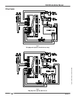
Included on the following pages are detailed wiring and
programming instructions for three common applications.
Figure 2: Simple Time Delayed Output
Figure 3: Electric Lock & Door Operator Sequencing
Figure 4: Vestibule Door Sequencing
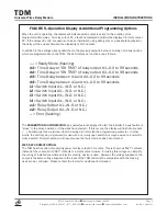
After successfully wiring the TDM for your application,
refer to Figure 5 for the operating display explanations
and additional programming options. For additional
technical assistance, please contact us toll-free at 1-800-
842-2545.
NOTICE:
These instructions are provided for your
convenience. Please verify your installation is in
compliance with all local electrical codes.
Section 3
Technical Data
Model....................................... TDM
Input Power.............................. 12-24V AC or DC
Power Consumption................ 2W Maximum
Output Contacts....................... Form C, Rated at 3 Amps
Relay Contact Rating............... 3A:120V AC; 3A:60V DC
Temperature Rating................ -22°F to 158°F
(-30°C to 70°C)
Weight...................................... <0.25 lbs.
Physical Size............................ 4.75"L x 2.125"W x 0.75"H
Section 4
Warranty
MS SEDCO guarantees this product to be free from manufacturing
defects for 1 year from date of installation. Unless MS SEDCO is
notified of the date of installation, the warranty will be in effect for
1 year from the date of shipment from our factory. If, during the
first year, our motion detector or support device fails to operate
and has not been tampered with or abused, the unit can be
returned prepaid to factory and it will be repaired free of charge.
After 1 year, the unit will be repaired for a nominal service charge.
This limited warranty is in lieu of all other warranties expressed
or implied, including any implied warranty of merchantability,
and no representative or person is authorized to assume for MS
SEDCO any other liability in connection with the sale of our
products. All warranties are limited to the duration of this
written warranty. In no event shall MS SEDCO be liable for any
special, incidental, consequential or other damages arising
from any claimed breach of warranty as to its products or
services.
Questions? Call us toll-free at 1-800-842-2545 or
visit us online at www.mssedco.com.
!
!
!
Summary of Contents for MA900n
Page 3: ...MA900 Installation and Owner s Manual 203936 Rev C ...
Page 4: ... 2005 The STANLEY WORKS ALL RIGHTS RESERVED 203936 Rev C MA900 Installation Manual 2 ...
Page 29: ... 2005 The STANLEY WORKS ALL RIGHTS RESERVED 203936 Rev C MA900 Installation Manual 27 Notes ...
Page 30: ... 2005 The STANLEY WORKS ALL RIGHTS RESERVED 203936 Rev C MA900 Installation Manual ...


