© 2005, The STANLEY WORKS. ALL RIGHTS RESERVED.
203936 Rev. C
MA900 Installation Manual
13
10. Remove the template.
11. If the door is made of metal, use a 25/64” bit to drill holes for
the Riv-nuts supplied, or a 3/8” bit to drill holes for the 1-5/8”
sex nuts supplied.
12. If the door is made of wood, use a 3/8” bit to drill holes for the
1-5/8” sex nuts supplied.
13. Attach the door shoe to the door using the two 1/4-20 x 1”
flat-head screws supplied.
14. Thread the rod into the door shoe.
15. Open the door to the desired fully open position.
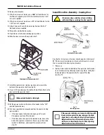
16. Slide the door arm onto the operator shaft.
Fig. 15
Attachment of arm to operator shaft
17. Install the operator arm retainer washer and screw to the
bottom of the operator shaft (see Fig. 15).
18. Use a 1/2” box end wrench to tighten the bolt that attaches the
door arm to the operator shaft.
Make certain this bolt is fully tight.
19. Set the power switch on the side of the header to the “Off”
position (power down).
20. Test door operation by manually pushing the door to its fully
open position.
•
If the door opens to the desired angle, go to Tune-In
Procedures section of this manual.
•
If the door does not open to the desired angle, loosen the
bolt on the operator output arm. Power up, set the mode
switch to Hold Open, and repeat the procedure from
step 15.
Install Door Arm Assembly - Inswing Door
Do not wear rings, watches or loose clothing
while installing or servicing the door operator.
Fig. 16
Inswing door arm assembly
See Fig. 16. In most cases the door should open to a minimum of
90˚. The door arm terminates in a block, which travels in a track
that is secured to the door by two brackets.
1. Power up.
2. Set the mode switch to Hold Open. The operator shaft rotates
to its mechanical stop (fully open) and stays there. Verify that
the dowel pin on the operator shaft is against the stop
(see Fig. 17).
Fig. 17
Full stop position
If the operator shaft does not come to a full stop with
the dowel pin against the stop, decrease the back
check time, as described in step 2 of Door Opening
Adjustments section of this manual. Increase the
stall force as described in step 3 of Door Opening
Adjustments section of this manual.
★
★
Summary of Contents for MA900n
Page 3: ...MA900 Installation and Owner s Manual 203936 Rev C ...
Page 4: ... 2005 The STANLEY WORKS ALL RIGHTS RESERVED 203936 Rev C MA900 Installation Manual 2 ...
Page 29: ... 2005 The STANLEY WORKS ALL RIGHTS RESERVED 203936 Rev C MA900 Installation Manual 27 Notes ...
Page 30: ... 2005 The STANLEY WORKS ALL RIGHTS RESERVED 203936 Rev C MA900 Installation Manual ...


