14
ENGLISH
(Original instructions)
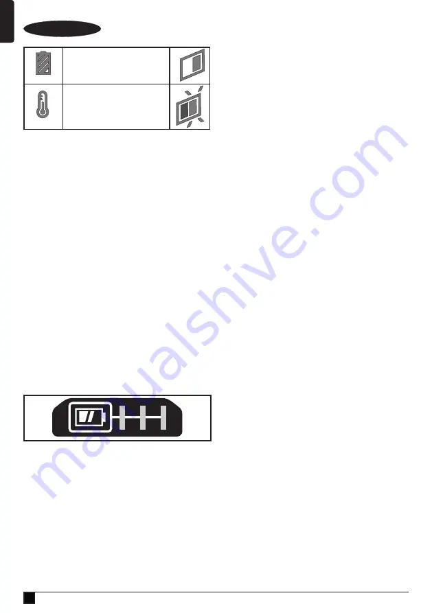
Fully Charged:
Green LED Solid
Hot/Cold Pack Delay:
Green LED Intermittent
Red LED Solid
Note:
The compatible charger(s) will not charge a faulty
battery pack. The charger will indicate a faulty battery pack by
refusing to light.
Note:
This could also mean a problem with a charger. If the
charger indicates a problem, take the charger and battery
pack to be tested at an authorized service centre.
Leaving the battery in the charger
The charger and battery pack can be left connected with the
LED glowing indefinitely. The charger will keep the battery
pack fresh and fully charged.
Hot/Cold Pack Delay
When the charger detects a battery that is too hot or too cold,
it automatically starts a Hot/Cold Pack Delay, the green LED
(21a) will flash intermittently, while the red LED (21b) will
remain on continuously, suspending charging until the battery
has reached an appropriate temperature. The charger then
automatically switches to the pack charging mode. This
feature ensures maximum battery life.
Battery state of charge indicator (Fig. C)
The battery includes a state of charge indicator to quickly
determine the extent of battery life as shown in figure B. By
pressing the state of charge button (15a) you can easily view
the charge remaining in the battery as illustrated in figure C.
Fitting and removing the battery (fig. D, E)
u
To fit the battery (15), line it up with the receptacle on the
tool (22). Slide the battery into the receptacle and push
until the battery snaps into place.
u
To remove the battery, push the battery release button
(15b) while at the same time pulling the battery out of the
receptacle as shown in figure E.
Changing or Installing a New Saw Blade (Fig. G,
H, I)
Warning!
To reduce the risk of serious personal injury, turn
tool off and remove the battery pack before transporting,
making any adjustments or removing/installing attachments or
accessories. An accidental start-up can cause injury.
Removing the Blade
u
Remove battery pack (15) from the saw.
u
Raise the arm to the upper position and raise the lower
guard (4) as far as possible.
u
Loosen, but do not remove the guard bracket front screw
(24) until the bracket (25) can be raised far enough to
access the blade screw (26). Lower guard will remain
raised due to the position of the guard bracket screw.
u
Depress the spindle lock button (28) while carefully rotat-
ing the saw blade (29) by hand until the lock engages.
u
Keeping the button depressed, use the other hand and the
hex side of the wrench provided to loosen the blade screw
(26). (Turn clockwise, left-hand threads.)
u
Remove the blade screw (26) using the hex side of the
wrench provided, the outer clamp washer (30) and blade
(29). The inner clamp washer (31) may be left on the
spindle (32).
Installing a Blade
u
Remove battery pack (15) from the saw.
u
With the arm raised, the lower guard (4) held open and
the guard bracket (25) raised, place the blade (29) on the
spindle (32) and against the inner blade clamp (31) with
the teeth on the blade pointing in the direction of rotation
as marked on the saw.
u
Assemble the outer clamp washer (30) onto the spindle
(32).
u
Install the blade screw (26) and, engaging the spindle lock
(28), tighten the screw (26) firmly with wrench provided
(turn counterclockwise, left-hand threads).
u
Return the guard bracket (25) to its original full down posi-
tion and firmly tighten the guard bracket screw (24) to hold
bracket in place.
Cut line guidance system
Warning!
Do not stare into work light. Serious eye injury could
result.
Note:
The battery must be charged and connected to the
mitre saw.
The cut line guidance system can only be turned On or Off by
the work light switch (16).
To cut through an existing pencil line on a piece of wood, turn
on the cut line guidance system using the work light switch
(16) (not with the main trigger), then pull down on the operat-
ing handle (2) to bring the saw blade close to the wood.
The shadow of the blade will appear on the wood. This
shadow line represents the material that the blade will remove
when performing a cut.
To correctly locate your cut to the pencil line, align the pencil
line with the edge of the blade’s shadow. Keep in mind that
you may have to adjust the mitre or bevel angles in order to
match the pencil line exactly.
Summary of Contents for Fatmax SFMCS701
Page 1: ...www stanley eu SFMCS701 ...
Page 2: ...2 1 17 4 14 4 15 14 2 3 10 19 18 15 20 16 3 6 7 10 11 12 13 3 10 16 5 3 11 13 8 9 ...
Page 3: ...3 15 15a 15 21 21b 21a 20 15 22 22 15 15b A B C D E F 10 10 ...
Page 4: ...4 1 1a 17 24 25 26 27 28 29 26 30 31 32 G H I J K 12 L 5 6 8 7 ...
Page 5: ...5 M 14 35 N O1 O2 O3 O4 ...
Page 6: ...6 19 37 P Q1 Q2 R1 R2 A B R3 ...


