1.3 The SR470 Rear Panel
1 – 19
10. Count step size: 1
11. Aux I
/
O configuration: Manual, high
12. Alarm: Audible
13. Display: On
Recalling factory default settings this way does not a
ff
ect the interface
configuration. The interface configuration can be restored to factory
defaults by power cycling the unit with the [ENet] ([6]) key pressed.
In this case, the following interface setup is recalled:
1. RS-232: Enabled
2. RS
=
232 baud rate: 9600
3. GPIB: Enabled
4. GPIB address: 8
5. TCP
/
IP interface: Enabled
6. IP Address: 0.0.0.0
7. Subnet: 0.0.0.0
8. Router: 0.0.0.0
9. Link speed: 100 Base-T
10. VXI-11, Telnet, and Raw socket interfaces enabled.
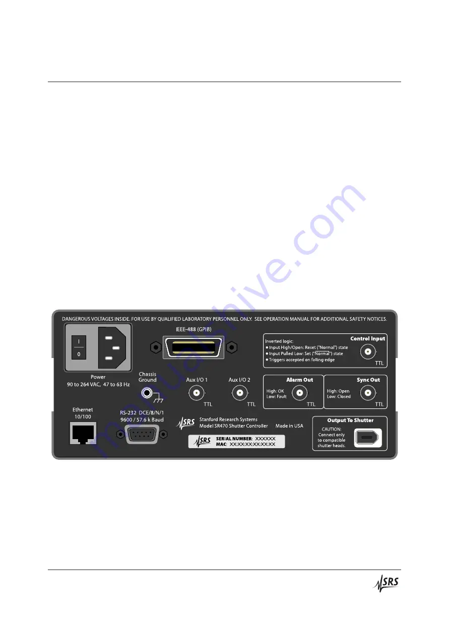
Figure 1.3: The SR470 rear panel.
1.3
The SR470 Rear Panel
The rear panel of the SR470 (see Figure 1.3) provides input and
output connectors for controlling the shutter, a TTL sync output, an
alarm output, two auxiliary I
/
O ports, a chassis-grounded binding
post, three remote interfaces, and the power entry module.
SR470 Shutter Controller


