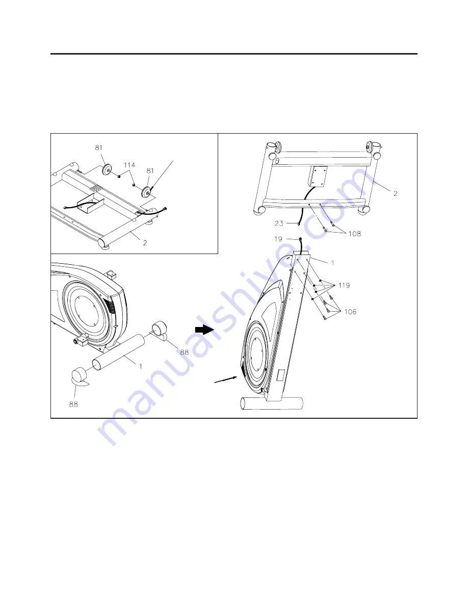
Place all parts from the box in a cleared area and position them on the floor in front of you. Remove all
packing materials from your area and place them back into the box. Do not dispose of the packing materials
until assembly is completed. Read each step carefully before beginning. If you are missing a part please
call our toll-free number for assistance
1 (800) 375-7520
or e-mail us at:
6
ASSEMBLY INSTRUCTIONS
NOTE: You will need to obtain assistance from another person for the following assembly.
A.
STEP 1
Refer to inset drawing A. Place the side of the
WHEELS(81)
with the longer shoulder toward the frame of
the
FRONT BASE(2).
Then attach the
WHEELS(81)
onto the threaded inserts of the
FRONT BASE(2)
with
NYLOCK NUTS(114).
Put a rug or some other protective
material under this corner of the
Plastic Covers to avoid damaging
the Plastic Covers.
Place the side of the WHEEL(81)
with longer shoulder toward the
side frame of the FRONT
BASE(2).
STEP 2
Remove the
ENDCAPS(88)
from the
STABILIZER
of the
MAIN FRAME(1).
One person should tilt the unit
up and hold it in position as shown above while the other person connects the
BASE CONNECTION WIRE
(23)
to the
LOWER CONNECTION WIRE(19),
and then inserts the
BASE FRAME(2)
into the
MAIN
FRAME(1)
and secures it with
BUTTON HEAD BOLTS(M8x1.25x16mm)(106)
and
LOCK WASHERS(M8)
(119).
Attach the crossing bar on the
FRONT BASE(2)
to the
MAIN FRAME(1)
with
BUTTON HEAD
BOLTS(M8x1.25x30mm)(108).
Lay the unit down and press the
ENDCAPS(88)
back on the
STABILIZER
of the
MAIN FRAME(1).
(No washers are used
here with bolts 108.)


