background image

F

REE

C

LIMBER

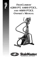
4200 PT, 4400 PT/CL, 

AND

4600 PT/CL

O

WNER

S

M

ANUAL

®

Summary of Contents for FREECLIMBER 4200 PT

Page 1: ...FREECLIMBER 4200 PT 4400 PT CL AND 4600 PT CL OWNER S MANUAL ...

Page 2: ...nd or other countries All other trademarks are trademarks of their respective companies StairMaster is a Rutledge Capital Company P N 22867 A Printed in the United States 2001 StairMaster Health Fitness Products Inc All rights reserved Corporate Headquarters 12421 Willows Road N E Suite 100 Kirkland WA 98034 800 635 2936 425 823 1825 Fax 425 823 9490 www stairmaster com Page iii ...

Page 3: ...all our Customer Service Department to receive a Return Material Authorization RMA prior to shipment StairMaster Health Fitness Products Inc will incur all freight charges for warranty parts ordered for a machine that is less than 45 days old The parts will be shipped to you via an overnight courier You are responsible for freight charges on warranty parts for machines that are more than 45 days o...

Page 4: ...SE SYSTEM The StairMaster FreeClimber exercise systems are vertical climbing machines with an independent step action The independent step action combined with the patented pedal geometry featured on all StairMaster steppers provides an aerobic workout equivalent to uphill running or climbing stairs but without the high impact pounding to the joints and muscles There are five FreeClimber models th...

Page 5: ...ELEMETRY HEART RATE 4400 4600 PT CL ONLY 15 Using the Transmitter Belt 15 Maintaining the Transmitter Belt 16 CONTACT HEART RATE 17 Using Contact Heart Rate 17 FREECLIMBER 4400 4600 PT CL CONSOLE 18 Display Window 18 Numeric Keypad 19 Entertainment Keypad 19 Intensity Level Keys 19 Stop Key 19 Workout Statistics 20 Exercise Program Keypad 21 The Quick Start Program 21 The Manual Program 21 The Fat...

Page 6: ...hine Status Codes 33 Quick Scan Programming 34 Configuration Code 34 FREECLIMBER 4200 PT CONSOLE 35 Top Window 35 Workout Setup 35 Timer 36 Bottom Window 37 Keypad 37 Quick Start Option 38 MAINTENANCE INSTRUCTIONS 39 Helpful Hints 39 Tool List 39 Maintenance Records 39 Initial Service 40 Preventive Maintenance 40 Cleaning 40 Inspecting 40 Lubrication 41 Battery Charge 42 Battery Disposal 42 TROUBL...

Page 7: ... Telemetry Heart Rate Test 51 Mechanical Troubleshooting 53 PARTS REMOVAL AND REPLACEMENT 56 Covers 56 Mid Cover 56 Top Cover 56 Shield 4600 PT CL 57 Bottom Cover 57 Console 58 Console Adjustment 4600 PT CL 58 Poly V and HTD Belt 58 Step Chain Retainer 59 Pedal Arm Return Spring 59 Step Chain 60 Spring Pulley 61 Drive Chain 61 Drive Shaft Assembly 62 Pedal 64 Leveling Arm 64 Pedal Arm 65 Pedal Pad...

Page 8: ...r FreeClimber Exercise Systems 5 Table 2 Fitness Rating Norms VO2max 29 Table 3 Recommended Preventive Maintenance Schedule 43 LIST OF ILLUSTRATIONS Figure 1 Major Parts 4600 PT CL 3 Figure 2 Major Parts 4200 PT and 4400 PT CL 4 Figure 3 Level Adjusting End Caps 6 Figure 4 DC Power Connector 7 Figure 5 Correct Exercise Postion 12 Figure 6 Transmitter Belt 16 Figure 7 FreeClimber 4400 4600 PT CL Sy...

Page 9: ...ssembly 4600 4400 PT CL 4200 PT 80 Figure 18 Drive Shaft Assembly Eccentric Hub Assembly 4600 4400 PT CL 4200 PT 81 Figure 19 Final Assembly Left 4400 4200 PT 82 Figure 20 Final Assembly Right 4400 4200 PT 83 Figure 21 Final Assembly Left 4400 CL 84 Figure 22 Final Assembly Right 4400 CL 85 Figure 23 Covers 4400 PT CL 4200 PT 86 Figure 24 Cover Removal 87 Figure 25 Cover Fasteners 88 Figure 26 Dri...

Page 10: ...EAD ALL INSTRUCTIONS BEFORE USING THE MACHINE To reduce the risk of electrical shock always unplug the external power supply from the AC wall outlet before cleaning maintaining or repairing To reduce the risk of burns electric shock or injury to persons 1 The external power supply should always be unplugged from the AC wall outlet before removing or installing parts Never make adjustments or repai...

Page 11: ...t operate where aerosol spray products are being used 10 Always wear insulated gloves when handling batteries 11 Do not crush incinerate or dismantle the battery The electrolyte contains sulfuric acid which can cause serious damage to eyes and skin Should this occur flush profusely with water and seek medical attention 12 Do not use the machine outdoors The safety level given by the design of this...

Page 12: ... facility in Tulsa Oklahoma your StairMaster FreeClimber exercise system was thoroughly inspected and tested to ensure proper operation The major parts of the machine are shown in Figures 1 and 2 Figure 1 Major Parts 4600 PT CL INTRODUCTION ...

Page 13: ...Page 4 Figure 2 Major Parts 4200 PT and 4400 PT CL INTRODUCTION ...

Page 14: ...ems Physical Dimensions Length 44 inches 104 cm Width at Front Leg 4400 PT CL 4200 PT 22 inches 56 cm Width at Front Leg 4600 PT CL 32 inches 82 cm Height 69 inches 176 cm Weight 4400 PT CL 4200 PT 126 pounds 55 kg 4600 PT CL 155 pounds 70 kg Power Supply Specifications 4600 4400 4200 PT U S Canada Japan 120 VAC 50 60 Hz 2 5 Amp 4600 4400 4200 PT International 230 VAC 50 60 Hz 2 5 Amp Battery Char...

Page 15: ...ine is level before you use it for the first time The four rubber end caps see Figure 3 are designed to compensate for uneven floors Each face of the caps is a different thickness Twist the caps to stabilize the machine Figure 3 Level Adjusting End Caps 3 Open the box you removed from the pedals The box contains either an external power supply 4600 4400 4200 PT only or a wall pack battery charger ...

Page 16: ...the left side cover see Figure 4 Figure 4 DC Power Connector 5 Place the power supply on the floor near an AC wall outlet To reduce the hazard of electrical shock place the power supply in a location away from the machine and away from exposure to perspiration You should not place your power supply on a carpet because it may over heat INSTALLATION INSTRUCTIONS ...

Page 17: ...tomer Service Department Refer to the Appendix for the appropriate phone number 9 If you have a 4600 4400 CL step on the pedals to check for proper operation Once you step on the pedals the console should display a software revision code and then show SELECT WORKOUT If it does not connect the battery charger to the connector on the lower left side If the console still does not power up contact our...

Page 18: ...ividuals should be particu larly cautious when using the machine for the first time Even though such individuals may not have histories of serious physical problems they may perceive the exercise to be far less intense than it really is resulting in the possibility of overexertion or injury 5 Although all equipment manufactured by StairMaster Health Fitness Products Inc has been thoroughly inspect...

Page 19: ... metric units Correct entry errors by pressing CLEAR before you press ENTER 5 The console will prompt you to enter your intensity level Enter your desired intensity level Correct entry errors by pressing CLEAR before you press ENTER 6 The console will prompt you to enter the workout time in one minute increments between 5 and 99 minutes Press 1 0 ENTER to exercise for ten minutes If you do not sta...

Page 20: ...llow the onscreen prompt to continue your work out after a rest period Cool Down 12 When you are finished with your workout the machine will slow down and the message GOAL ATTAINED will be displayed You can cool down on the machine by continuing to step The console timer will continue to count up from the selected time and the intensity level will default to level 3 If there is a time limit set on...

Page 21: ...ing your knees lock out Feet Place 3 4 of each foot on the ped als heels slightly off the edge with your toes facing forward Chest Shoulders Keep your shoulders square and centered over your hips with your chest lifted Hands Rest your hands lightly on the side rails or front handlebars Excessive leaning on the side rails can re duce calorie burn by up to 20 Elbows Keep both elbows slightly bent If...

Page 22: ...ut session During the validation phase the console will not recognize contact heart rate signals Contact heart rate after the initial contact sensor signal is detected the console will enter a validation phase requiring a good heart beat signal within 10 to 15 seconds or until the system acquires a valid signal During the validation phase the console will not recognize telemetry heart rate signals...

Page 23: ... will detect either input signal during a workout session but only one at a time and only until the other signal terminates TELEMETRY ONLY locks out contact heart rate signals and will only detect telemetry signals HAND ONLY locks out telemetry signals and will only detect contact heart rate signals BOTH HR OFF turns off the ability to detect any signal at all Used in rare situations where there i...

Page 24: ...ng a valid signal A microprocessor in the console calculates the heart rate and displays it in beats per minute on the console Using the Transmitter Belt Before you put the transmitter belt on wet the two electrode patches the grooved rectangles on the reverse side of the belt Secure the transmitter belt as high under the pectoral muscles chest as is comfortable The transmit ter belt should fit sn...

Page 25: ...is working and retest the machine Verify that the console software has been set up properly for heart rate detection see pg 13 14 Figure 6 Transmitter Belt Maintaining the Transmitter Belt Clean the chest belt regularly with mild soap and water then dry thoroughly residual sweat and moisture keep the transmitter active and drain the battery in the transmitter Do not use abrasives or chemicals such...

Page 26: ...account for 5 7 of the population These individuals should opt for the Polar chest strap method of heart rate monitoring Most people between 93 95 will not have a problem with the system provided interference from movement is minimal Using Contact Heart Rate Contact heart rate input signals are acquired only during contact between your hands and the stainless steel sensors on the handrails To use ...

Page 27: ...ies The real time amount of calories burned is continually updated and displayed in the upper right section of the display window Interval Timer The interval timer is displayed below the Time The interval timer counts down time left within each interval Heart Rate Current heart rate is displayed below the Calories next to the heart icon Workout Option Profile A profile of the selected exercise pro...

Page 28: ... Specifica tion for Fitness Equipment C S A F E port to a connected C S A F E or compatible system If a system is not connected pressing these keys will have no effect Volume Up Down Increases or decreases the volume level of the audio source Mute Removes the audio sound from the headphones Channel Up Down Changes the channel of the commercial entertainment system INTENSITY LEVEL KEYS The exercise...

Page 29: ...ors per mile Level Shows the current intensity level between 1 the easiest and 20 the hardest Watts Displays the exercise intensity in watts 746 watts 1 horsepower METs Gives you the relative energy cost of exercise MET stands for mul tiples of the resting metabolic rate While you are sitting quietly your body consumes oxygen at the rate of about 3 5 milliliters per kilogram of body mass per minut...

Page 30: ... have selected a program the prompts are ENTER BODY WEIGHT type in your body weight in pounds or kilograms if your console is set to metric units ENTER LEVEL 1 20 select your intensity level with level 1 being the easiest and level 20 the hardest ENTER TIME 5 99 select the workout duration in one minute increments from 5 to 99 Press 0 in the MANUAL and CONSTANT HEART RATE program to workout for an...

Page 31: ...is indicated on the profile and any changes in the intensity level will not change the look of the remaining profile The Speed Intervals Program The Speed Intervals program is a workout with 8 rest intervals and 7 exercise intervals that alternate speed intensity level changes You can change the REST interval speed level and the EXERCISE interval speed level indepen dently using the level keys For...

Page 32: ...y the following equation 220 Age x 70 Choose a different target heart rate between 80 and 180 beats per minute at any time during the work out by using the numeric keypad to enter the new target heart rate followed by the ENTER key The following messages may be shown during a workout CHECK HR BELT The heart rate signal has been missing for the last 30 seconds in telemetry signal detection HR BELT ...

Page 33: ...r the four listed assumptions For example exercising at a given workload for only a few minutes can involve an insufficient amount of time for many indi viduals to achieve a true steady state To ensure that a steady state has been achieved the heart rate should be measured after two minutes of exercise at a given workload and again after the third minute of exercise at that workload These two hear...

Page 34: ...dual s age predicted maximal heart rate is higher than that person s true maximal heart rate then his her estimated VO2 max will be an overestimation of the correct or actual value The final assumption addresses the issue of mechanical efficiency Oxygen uptake at any given work rate can vary by approximately 15 between different individuals Therefore individuals vary in the amount of oxygen they r...

Page 35: ... participant from taking part in an exercise test until appropriate medical clearance was obtained PHYSICAL ACTIVITY READINESS QUESTIONNAIRE PAR Q 1 Has your doctor ever said you have a heart condition and recom mended only medically supervised physical activity 2 Do you have chest pain brought on by physical activity 3 Have you developed chest pain within the past month 4 Do you tend to lose cons...

Page 36: ...the 2nd and 3rd minute are not within 5 beats min of each other then that work rate is maintained for an additional minute At the end of the 4th minute the heart rate is compared to the heart rate at the end of the 3rd minute If the heart rates are within 5 beats min then the heart rate during the 4th minute is plotted against the work rate If the heart rate at the end of the 3rd and 4th minute ar...

Page 37: ...l 6 M ETs Second W ork Level 5 M ETs Third W ork Level 9 M ETs Fourth W ork Level 11 M ETs Third W ork Level 8 M ETs Fourth W ork Level 10 M ETs FIT TEST PROTOCOL StairMaster CV Products Test Complete Display Results If HRs 115 If HRs 115 If HRs 115 Y Y Y Test fails if 2 stages of at least 115 bpm are not obtained FREECLIMBER 4400 4600 PT CL CONSOLE ...

Page 38: ...Physical Ability Test CPAT approved by the International Association of Fire Fighters IAFF and reviewed by the U S Justice Depart ment requires each candidate to step on the Stepmill at a predetermined stepping pace for a specific period of time There are two fire fighter specific Stair Climb Test programs The first test is the CPAT Stair Climb Test The second test is a modified version of the CPA...

Page 39: ...CFD Stair Climb Test Fit Test 3 The first phase is a warm up interval at an intensity of 56 steps min and lasts 60 seconds followed by a 60 second rest period no stepping At the end of the rest period the time counter will reset to zero The second phase is at an intensity of 68 steps min and lasts for 5 minutes 12 seconds Turning on the NYCFD Stair Climb Test 1 Press 9 2 ENTER on the console keypa...

Page 40: ...le selections Once in this mode pressing LEVEL backs up through the selections pressing ENTER then selects that item If another test level is available at this point the SELECT ENTER process is repeated Pressing 1st or 2nd ENTER selects that item directly Pressing CLEAR exits any of the special access modes Custom Codes 3 0 change workout time limit between 5 to 99 minutes 3 1 change units MPH or ...

Page 41: ...rrent language Press the SELECT key to scroll through the other options Press ENTER to change the option 5 Adjust the contrast on the LCD screen by pressing LEVEL 3 5 The console will display CONTRAST ADJ Press ENTER The console will then display the current contrast number Press the LEVEL and LEVEL keys to increase or decrease the contrast The changed value will remain on exit 6 Reset the console...

Page 42: ... The console will display RUN HOURS XXXXX 2 Display the number of workouts by pressing LEVEL 4 1 The console will display WORKOUTS XXXX 3 Display the total distance covered up to date by pressing LEVEL 4 2 The console will then display DISTANCE XXXX 4 Display the console software revision number by pressing LEVEL 4 3 The console will display CONS 92111 XXX 5 Display the machine type by pressing LE...

Page 43: ...cing After each maintenance period reset the counter 7 1 Reset Service 1 Reset the maintenance hour counter by pressing LEVEL 7 1 The console will dusplay RESET SERVICE Press ENTER The console will display DONE Press CLEAR to return to the starting screen Configuration Code The FreeClimber console supports other StairMaster exercise systems It is important to verify that the machine configuration ...

Page 44: ...being displayed Figure 9 4200 PT Console Diagram TOP WINDOW The top LCD window displays information while you set up your workout It also displays elapsed time during your workout or during your rest period Workout Setup 1 While the console is in the ATTRACT mode either press START STOP or step on the pedals Look at the top LCD window 2 The arrow pointing to the word Program should be flashing and...

Page 45: ...NTER SELECT when it is correct If you selected MANUAL your workout will start at speed level 3 Level 1 is the slowest and level 20 is the fastest Use the or ARROW to adjust the climbing speed once your workout begins 6 The arrow pointing to the word Time will flash and the number 15 will be displayed Press the or ARROW to adjust the length of your workout between 5 and 45 minutes 7 Press ENTER SEL...

Page 46: ... arrow points to the word Scan all workout statistics are scrolled Press ENTER SELECT during your workout to lock the bottom display window on any one statistic For instance press ENTER SE LECT three times to lock the display on the total number of floors climbed Press ENTER SELECT two more times to resume scrolling the statistics Dur ing rest periods only Calories Floors and Distance are shown ev...

Page 47: ...od is started If pressed during a rest period the console returns to the ATTRACT mode QUICK START OPTION You can quickly start the MANUAL program P1 by pressing ENTER SELECT twice double clicking at the start of workout setup The workout statisics are based on a 150 pound person the climbing speed starts at level 3 and the workout time is set to 15 minutes Use the or ARROW to adjust the climbing s...

Page 48: ...multimeter wire stripper crimper tool allen wrench set sizes 5 64 1 4 external snap ring pliers shop goggles or other eye protection torque wrench socket set or nut driver set sizes 1 4 3 4 in 1 16 increments MAINTENANCE RECORDS For ease of maintenance the 4400 4600 PT CL console will keep track of hours number of workouts time between last servicing etc You can quickly access any of the custom me...

Page 49: ...r The preventive maintenance schedule is summarized in Table 3 The schedule is based on normal usage in a commercial health club environment adjust the schedule to meet actual machine usage Refer to the Parts Removal and Replacement section for all disassembly and assembly instructions Cleaning 1 DO NOT USE GLASS CLEANERS OR ANY OTHER HOUSEHOLD CLEANERs ON THE CONSOLE Clean the console daily with ...

Page 50: ...ntire length of the chains with 30W motor oil 3 Remove the drive chain and step chains every three months to thoroughly clean and lubricate them Use a mild degreaser and a stiff brush to remove dirt and corrosion from the chains 4 Unhook the pedal arm return springs from the spring hanger every week To protect them from corrosion wipe the entire length of each pedal arm return spring with a cloth ...

Page 51: ... less than 6 1 VDC charge the battery Plug the wall pack battery charger into the connector located near the bottom of the left bottom cover Charge the battery for approximately 24 to 48 hours and then recheck it It is okay to use the machine while the battery charger is connected Battery Disposal When ordering new batteries you will need to properly dispose of recycle your old lead acid batteries...

Page 52: ... y r e v E r o s h t n o m 0 0 9 r e t f a s r u o h y r d n a e l C g a r i t l u M e s o p r u p e s a e r g g n i r p S y e l l u P s t f a h S d n a n a e l C e t a c i r b u l 3 y r e v E r o s h t n o m 0 0 9 r e t f a s r u o h y r d n a e l C g a r i t l u M e s o p r u p e s a e r g l a d e P d n a s t f a h S g n i l e v e L s n i P m r A d n a n a e l C e t a c i r b u l 3 y r e v E r o...

Page 53: ...parts are inoperable they must be replaced Opening the console or the power supply will void the warranty 4600 4400 PT 1 Use a voltmeter set on VAC to verify that the AC wall outlet has 100 to 120 VAC or 220 to 240 VAC if applicable If you do not have a voltmeter plug in an alternate AC powered device e g a lamp If the device does not work when plugged into the electrical outlet consult an electri...

Page 54: ...the console lift the console up and disconnect the 20 pin main cable from the console 9 Test for 12 to 19 VDC in pins 1 and 10 in the main cable connector Replace the main cable if the voltage reading is not the same as in step 7 10 If all voltage readings have been within the specified range and the console will not power up the console should be replaced Alternator Test 11 Check for loose wiring...

Page 55: ...gs recorded are both high or both low Resistor Test 15 Remove one wire from the load resistor see Final Assembly Figure and place one lead from the voltmeter on each of the threaded posts on the load resistor Replace the load resistor if the voltmeter does not read 0 5 Ohms 10 4600 4400 CL Battery Test 1 Remove the mid cover and top covers and unplug the battery from the power control board Locate...

Page 56: ...re from the B terminal on the alternator Remove the brown wire from the field terminal on the alternator Place a short wire with alligator clips on the B terminal and the field FLD terminal of the alternator Step on the machine for approximately 10 to 15 seconds If full resistance is achieved during this time your alternator has correct current flow If no resistance is achieved replace the alterna...

Page 57: ...yboard 6 2 Test serial port 6 3 Test alternator 6 4 N A 6 5 N A 6 6 Test Tach 6 7 6 9 N A Display Test During the display test the console screen alternates between all LCD segments turned on and the sample program profile screen at a 2 second rate 1 Press LEVEL 6 0 ENTER The console will display DISPLAY TEST 2 All LCD segments will turn on for 2 seconds and then a sample program profile will be d...

Page 58: ... then display either PASS or FAIL Replace the console if it fails this test Alternator Test Use this test to verify the alternator field routines of the console You will need to briefly exercise on the machine for this test 1 Press LEVEL 6 3 to start the test 2 For Field on press LEVEL Step on the machine for approximately 10 to 15 seconds If full resistance is achieved during this time your conso...

Page 59: ...s or the main cable Error Reporting The console will display various error messages in the display window The total amount of errors will be displayed in the upper right numeric window Note that only the highest priority reported error will be displayed Errors are handled in two ways One as a non fatal WARNING which will display the text message but continue system operation until the user presses...

Page 60: ...ving interfering signals the contact heart rate system may be inhibited Take your hands off the handle sensors for about 20 seconds and watch the heart display If it flashes on and off the telemetry heart rate is picking up interfering signals and the machine must be moved away from the source of the interference or the telemetry heart rate input must be disabled see the heart rate monitoring sect...

Page 61: ...s not show or if your heart rate is not displayed on the console then you have a problem with either the console chest strap or heart rate receiver 3 Verify that the console software has been set up to receive telemetry see the heart rate monitoring section of this manual Note that holding the contact heart rate sensors if enabled can inhibit the telemetry heart rate input from working 4 Test your...

Page 62: ...ve the pedal arms If the noise no longer exists check the condition of the alternator If the noise is still present go to step 4 Disconnect the DC power cable if you have a 4600 4400 4200 PT or unplug the connector from position J4 on the power supply circuit board if you have a 4600 4400 CL Spin the alternator pulley with your fingers It should spin freely and remain spinning for at least two rev...

Page 63: ... the drive hub assembly Check the condition of the drive sprocket teeth The teeth should not be unevenly worn Replace the worn sprocket s The drive sprockets work independently of one another Each sprocket should turn freely in one direction and lock when turned in the other direction Replace an inoperable drive sprocket Remove the drive shaft Inspect the bearings in the drive hub Replace the driv...

Page 64: ...essary The Poly V pulley should spin freely If it does not replace the eccentric shaft assembly 10 Inspect the HTD pulley for excessive wear and smoothness of operation If the pulley is worn replace it If it does not spin freely remove the first reduction shaft and inspect the bearings 11 Reinstall all parts ensuring the proper tension of the Poly V and HTD belts and the drive chain see Figure 30 ...

Page 65: ...ttom cover Mid Cover 1 Use the fastener removal tool to remove each of the four fastener pins on the mid cover see Figure 23 2 Stand on the pedals and keep them on the floor 3 Slide the mid cover down and away from the machine Remove the cover from the frame tube Carefully let both pedals return to the upper stops Top Cover 1 4400 PT CL 4200PT Remove the mid cover and the console 2 Release the pin...

Page 66: ...Disconnect the DC power cable from the connector located on the bottom side of the left bottom cover 3 Remove the fastener located on each side of the lower edge of the bottom cover see Figure 24 4 4400 PT CL 4200 PT Kneel in front of the machine facing the cover seam Push in and hold both sides of the lower cover to disengage the locking tabs at the joint between the upper and lower covers Use yo...

Page 67: ...to desired viewing angle and then tighten the wing nut POLY V AND HTD BELT 1 Remove the bottom cover 2 Loosen the adjustment bolt that mounts the alternator to the slotted alternator brace and the pivot adjusting bolt and nut Swing the alternator down 3 Remove the Poly V belt 4 Slide the HTD belt toward you and off the HTD pulley Remove the belt from the machine 5 Reinstall the HTD belt PARTS REMO...

Page 68: ...side of the belt see Figure 30 9 Tighten the alternator adjustment bolt Verify 1 4 0 6 cm of play in the belt and reinstall the bottom cover STEP CHAIN RETAINER 1 Remove the bottom cover 2 Loosen and remove the two step chain retainer bolts These bolts are also the top two mounting bolts for the drive hub assembly 3 Reverse the removal procedures to install the step chain retainer Make sure there ...

Page 69: ... the bottom cover 2 Remove the step chain retainers 3 Support the pedal arm Unhook the pedal arm return spring from the spring hanger Lift the step chain up and off the clutch sprocket and lower the pedal arm to the floor 4 Remove the double pitch master link PN 21298SV and bearing sleeve assembly from the step chain connection point on the pedal arm 5 Remove the master link from the spring chain ...

Page 70: ...t of multi purpose grease to the pulley shaft 6 Slide the pulley and washer onto the shaft Install the snap ring 7 Route the spring under the spring pulley 8 Hook the end of the spring over the spring hanger Do not twist the spring 9 Reinstall the covers DRIVE CHAIN 1 Remove the bottom cover PARTS REMOVAL AND REPLACEMENT TO REDUCE THE RISK OF EYE INJURY WEAR EYE PROTECTION WHEN REMOVING SNAP RINGS...

Page 71: ...ssembly section 6 Lubricate the chain with 30W motor oil and wipe off the excess 7 Reinstall the covers DRIVE SHAFT ASSEMBLY 1 Remove the bottom cover 2 Remove the step chain retainers 3 Support the pedal arm Unhook the pedal arm return spring from the spring hanger Lift the step chain up and off the clutch sprocket and lower the pedal arm to the floor Repeat on the other side 4 Remove the snap ri...

Page 72: ...h sprockets are positioned correctly the wide shoulder of the sprocket should be facing away from the hub on both sides 11 Chain Tension The drive shaft is mounted in an eccentric hub Rotate the hub so the marked hole is in the 12 o clock position lining up four holes in the hub with the four holes in the frame Use this hub position when reinstalling the drive chain since the distance between the ...

Page 73: ...ING ARM 1 Remove the pedal 2 Remove the bottom cover 3 Remove the snap ring that secures the leveling arm to the leveling arm shaft see Figure 19 4 Slide or gently tap the leveling arm off the shaft 5 Clean the shaft and the pin with a cloth dampened with 30W motor oil before reassembly 6 Reverse the removal instructions to reinstall the leveling arm PARTS REMOVAL AND REPLACEMENT TO REDUCE THE RIS...

Page 74: ...an the pedal arm shaft and leveling arm pin with a cloth dampened with 30W motor oil before reassembly 8 Reverse the removal procedures to reinstall the pedal arm PEDAL PAD 1 The pedal pad wraps around the pedal and locks into place under the pedal Separate the pedal pad from the pedal by grabbing the bottom of the pedal and pulling down and out 2 Lift the other side of the pedal pad up and remove...

Page 75: ...c shaft assembly 4 Remove the set screw from the transmission sprocket see Figure 21 Remove the sprocket and key from the shaft 5 Hold onto the HTD sprocket and pull the shaft out of the hub 6 Reassemble in the reverse order Ensure the belts are properly tensioned refer to the Poly V and HTD belt section HANDLEBAR 4400 PT CL 4200 PT 1 Remove the console and separate the left and right top cover 2 ...

Page 76: ...e contact heart rate cables 5 Reverse the removal procedures to install the new upper handle assembly SIDE HANDRAILS 4600 PT CL 1 Disconnect the left and right contact heart rate cables from the back of the console 2 Remove the two mounting screws from the top and bottom shield see Figure 20 and remove the shields from the upper handle assembly 3 Remove the four handrail adapter screws from the up...

Page 77: ...ch wire attached to the alternator see Final Assembly Diagram Remove the wires from the alternator 2 Loosen and remove the alternator adjusting bolt on the slotted brace Remove the Poly V belt Inspect the belt for wear and replace the belt if it is cracked cut or is otherwise damaged 3 Loosen and remove the nyloc nut from the alternator post Remove the alternator from the frame 4 Reverse the remov...

Page 78: ...le receptacle if a properly grounded outlet is not available The adapter should be used only until a prop erly grounded outlet sketch A can be installed by a qualified electrician The tab extending from the adapter must be connected to a permanent ground such as the metal screw on the outlet cover This may vary for International power supplies GROUNDING INSTRUCTIONS Figure 10 Grounding System DANG...

Page 79: ...ol lowing measures Reorient or relocate the receiving antenna Increase the separation between the equipment and receiver Connect the equipment into an outlet on a circuit different from that to which the receiver is connected Consult the dealer or an experienced radio TV technician for help CANADIAN DOC CLASS B COMPLIANCE This digital apparatus does not exceed the Class B limits for radio emission...

Page 80: ... 425 814 0601 www stairmaster com E mail customerservice stairmaster com INTERNATIONAL OFFICES AND DISTRIBUTORS For technical assistance and a list of distributors in your area please call or fax one of the following numbers INTERNATIONAL DIVISION ASIA PACIFIC HEADQUARTERS 425 823 1825 Telephone Fax 81 45 590 5686 FAX 425 820 7505 E mail stairintl aol com E Mail intlservice stairmaster com EUROPE ...

Page 81: ... 333 3060 Southern City of Industry CA 91745 Colorado 12860 W Cedar Dr 303 763 5833 Suite 106A Lakewood CO 80228 Florida 11310 Satellite Blvd 407 857 9234 Orlando FL 32821 Georgia 1721 C Oakbrook Dr NE 404 446 8663 Norcross GA 30093 Illinois 5303 Ninth Ave 708 352 3665 Countryside IL 60525 Maryland 899 Airport Rd Ste E 410 768 5586 Glen Burnie MD 21061 Massachusetts 13 Wheeling Ave 617 932 6570 Wo...

Page 82: ...00 Montrose Ave 215 921 4480 Laureldale PA 19605 Pennsylvania East 320 Constance Dr 215 443 0912 Warminster PA 18974 Pennsylvania West 920 Vista Park Rd 412 788 1613 Pittsburgh PA 15205 Tennessee 2934 Brooks Road 901 396 5031 Memphis TN 38116 Texas Northeast 11420 Ferrell Dr Ste 300 214 869 1855 Dallas TX 75234 Texas South 4738 Cotton Belt 210 661 5497 San Antonio TX 78219 Texas Southeast 4301 S P...

Page 83: ...Page 74 APPENDICES Figure 11 Parts Needing Periodic Maintenance ...

Page 84: ...Page 75 APPENDICES Figure 12 Final Assembly Left 4600 PT ...

Page 85: ...Page 76 APPENDICES Figure 13 Final Assembly Right 4600 PT ...

Page 86: ...Page 77 APPENDICES Figure 14 Final Assembly Left 4600 CL ...

Page 87: ...Page 78 APPENDICES Figure 15 Final Assembly Right 4600 CL ...

Page 88: ...Page 79 APPENDICES Figure 16 Covers 4600 PT CL ...

Page 89: ...Page 80 APPENDICES Figure 17 Pedal Arm Assembly First Reduction Shaft Assembly 4600 4400 PT CL 4200 PT ...

Page 90: ...Page 81 APPENDICES Figure 18 Drive Shaft Assembly Eccentric Hub Assembly 4600 4400 PT CL 4200 PT ...

Page 91: ...Page 82 APPENDICES Figure 19 Final Assembly Left 4400 4200 PT ...

Page 92: ...Page 83 APPENDICES Figure 20 Final Assembly Right 4400 4200 PT ...

Page 93: ...Page 84 APPENDICES Figure 21 Final Assembly Left 4400 CL ...

Page 94: ...Page 85 APPENDICES Figure 22 Final Assembly Right 4400 CL ...

Page 95: ...Page 86 APPENDICES Figure 23 Covers 4400 PT CL 4200 PT ...

Page 96: ...Page 87 APPENDICES Figure 24 Cover Removal ...

Page 97: ...Page 88 Figure 25 Cover fasteners APPENDICES ...

Page 98: ...Page 89 APPENDICES Figure 26 Drive Chain tensioning ...

Page 99: ...Page 90 APPENDICES Figure 27 Belt Tension ...

Reviews: