background image

BAST_

02.FM

24

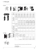
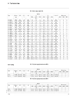
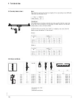
8    Wearing parts

8.1 Hoist  

8.2 Trolley

Replacement and repairs may only be performed by skilled personnel!

4

2

1

Designa-

tion

ST05

ST10

ST20

ST30

ST32

ST50

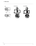
ST 60

1*1

Chain

331 005 9

331 006 9

331 001 9

331 004 9

331 004 9

331 013 9

331 023 9

2 Chain drive

nBh

32 320 96 30 0

kBh

32 320 96 30 0

nBh

14 320 00 41 0

kBh

14 320 01 41 0

nBh

16 320 00 41 0

kBh

16 320 01 41 0

nBh

13 320 00 41 0

kBh

13 320 01 41 0

nBh

17 320 00 41 0

kBh

18 320 02 41 0

nBh

18 320 00 41 0 

kBh

18 320 01 41 0

nBh

19 320 00 41 0 

kBh

19 320 01 41 0

3

Chain 

stopper

32 320 01 27 0 14 320 01 27 0 16 320 01 27 0 17 320 00 27 0 17 320 00 27 0

18 320 02 27 0

18 320 02 27 0

4

Brake/

slipping

clutch

32 320 90 30 0

-

-

-

-

-

-

5

Brake/

brake set

-

E21

14 320 09 64 0

E31

16 320 39 64 0

E31

16 320 39 64 0

E40/42

567 167 0 -100V
567 168 0 -190V
567 169 0 -240V
567 170 0 -290V

E40/42

567 167 0 -100V
567 168 0 -190V
567 169 0 -240V
567 170 0 -290V

E40/42

567 167 0 -100V
567 168 0 -190V
567 169 0 -240V
567 170 0 -290V

E22

14 320 10 64 0

E32

16 320 40 64 0

E32

16 320 40 64 0

6 Chain box 32 320 00 26 0

32 320 03 20 0

*2

12m

35 322 04 32 0

25m

33 320 26 26 0

8m

35 32204 32 0

16m

33 320 26 26 0

6m

35 320 04 32 0

10m

33 32026 26 0

6m

17 320 00 32 0

20 m

18 322 00 32 0

8m

18 320 00 26 0

12m

18 322 00 32 0

8m

18 320 00 26 0

12m

18 322 00 32 0

7

Suspen-
sion bolt

32 322 10 92 0

-

-

-

-

-

-

8

Suspen-
sion bolt

-

14 320 00 24 0 16 320 00 24 0 13 320 00 24 0

17 320 00 24 0

18 320 00 24 0

18 320 00 24 0

9 Single-fall 

bottom

hook block

125 kg

32 320 00 50 0

250 kg

32 320 01 50 0

14 320 01 59 0 16 320 02 59 0 17 320 00 59 0 17 320 00 59 0

18 320 00 59 0

18 320 00 59 0

10

Two-fall 

bottom

hook block

32 320 00 50 0 14 320 01 50 0 16 320 03 50 0 13 320 01 50 0 17 320 01 50 0

18 320 01 50 0

19 320 01 50 0

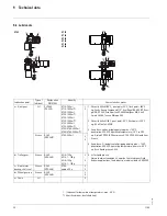
Designation

12

Brake disc

SF .. ... 123

567 100 0

SF .. ... 133

567 100 0

13 Brake housing

SU-A 14 .. 1..

51 250 79 37 0

SU-A 14 .. 2..

51 250 78 37 0

15

Wheel

‡

50

a

b

01 250 00 41 0

‡

63 - KE-T

a

02 250 01 40 0 

b

02 250 01 41 0

‡

63 - KF. 10

a

02 250 03 40 0 

02 250 02 41 0

‡

80

a

03 250 01 64 0

b

03 250 00 64 0

‡

125

a

05 250 04 40 0

b

05 250 03 41 0

*1 Please state length
*2 for chain hoist with KE-T trolley
nBh = standard headroom
kBh = short headroom

10.06

Summary of Contents for ST 0501-16

Page 1: ...ST Chain hoists_ Operating and Maintenance Instructions ...

Page 2: ...plicable regulations accident prevention regulations and prevailing conditions and have proven their ability Skilled electrician A skilled electrician possesses knowledge and experience on electrical equipment arising from specialist training and with knowledge of the applicable standards and regulations is able to assess the work with which he is entrusted and detect and avoid possible risks Defi...

Page 3: ...issioning 4 1 Checklist for commissioning 13 5 Operating 5 1 Duties of crane operator 14 5 2 Operating control pendant 15 5 3 Emergency stop 15 6 Maintenance 6 1 Maintenance work 16 6 2 Maintenance intervals 16 6 3 Hook 17 6 4 Load chain 17 6 5 Checking function of slipping clutch 18 6 6 Adjusting slipping clutch 18 6 7 Hoist motor brake 20 6 8 Oil change 20 6 9 Travel motor brake 21 6 10 Oil chan...

Page 4: ... marked with this symbol may only be opened by qualified persons or suitably instructed personnel Warning of suspended load It is forbidden for persons to stand under suspended loads This entails risks to life and limb Safety in operation Information marked with this symbol must be observed to avoid damage to the chain hoist or the goods transported 1 2 Operating instructions Read carefully and fo...

Page 5: ...x on the chain hoist but for example in a stationary control cabinet 1 4 Safety conscious operation The ST chain hoists are constructed according to the state of the art and equipped with a slipping clutch as overload protection In spite of this dangers may arise from incorrect use or use for an unintended purpose The operator see page 2 is responsible for ensuring that work is carried out with sa...

Page 6: ...in North America c Version without control STAHL chain hoists are available without control The switchgear e g contactors and transformer are then not supplied The rectifier for activating the brake remains part of the supply Safety note if the hoist is supplied without control it is recommended that the custo mer install a phase monitoring relay If the control is not installed in the terminal box...

Page 7: ...trol pendant 9 Plug for travel drive 10 Plug for mains connection 11 Socket for control pendant 12 Socket for travel drive 13 Socket for mains connection 14 Suspension hook 15 Suspension eye 16 Bottom hook block single fall 17 Load hook 18 Bottom hook block 2 fall 19 Control pendant 20 Emergency off Some illustrations include options 11 05 ...

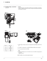
Page 8: ...ST05 see page 12 3 2 Installing trolley 3 2 1 Adjusting trolley to runway flange 1 Adjust play of wheel flanges see sketch and table 2 Tighten nut with specified torque see page 12 3 Fit screw retentions Suspend the chain hoist in the centre of the trolley Grease wheel gearing Use only original spare parts for modifying the flange width ST05 ST10 ST60 11 05 ...

Page 9: ...ad screw c See sketch KFN 10 32 with ST10 ST20 ST32 ST50 ST60 1 1 Fit suspension piece with suspension bolt a to chain hoist Note installation position of suspension piece Lock bolt a with locking plate b and cheese head screw c See sketch 2 Slide trolley onto runway or push on from below after swivelling the side cheeks up 3 Check that screws and nuts are tightened with specified torque see page ...

Page 10: ...lide trolley onto runway or push on from below after swivelling the side cheeks up 3 Check that screws and nuts are tightened with specified torque see page 12 4 The screw retentions must be fitted KFK 5 Turn wheel d by means of cam e until it is in contact with the running surface of the runway Tighten screw f N B The guide roller must be flush with the wheels a b c f e d d W0761 KFN 63 2 1 KFK K...

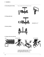
Page 11: ...st and secure 3 5 Fitting guide rollers 3 6 Runway endstop 3 7 Fitting and securing chain box Lubricate chain with the chain lubricant supplied Chain box must be able to move freely Max length of chain see sticker on chain box KFN KFK 10 32 B t 260 KFN KFK 63 B t 300 ST 10 ST20 ST30 ST 32 ST50 ST60 ST 05 ...

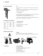
Page 12: ...s via a cable gland 3 9 Checking screw connections Chain guide attachment Distance bolt on trolley Trolley suspension 1 Self locking self tapping screws ST05 2 Plug connection 3 Cable gland in plastic 3 10Netzanschluss herstellen Safety note The chain hoist may only be connected by a skilled electrician The mains cable must meet the specifications given in the technical data see page 28 3 11Disman...

Page 13: ...y clean free of grease and paint even end stops present Check tightening torque of screw connections of suspension piece or trolley sus pension Open step of travel drive clean and greased During the following test steps you must be able to activate the emergency off but ton at all times Check function of chain hoist Direction of movement must correspond to the symbols on the control pendant If not...

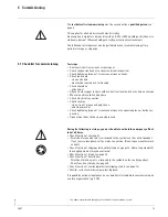
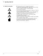
Page 14: ...orrectly do not leave suspended loads unat tended Control and emergency stop devices must be within easy reach Do not place your hand between edges which may pinch or cut If the chain should become slack tauten it at slow speed before lifting The slipping clutch is a safety device It must not be activated during normal operation Approach the final positions for lifting lowering and travelling in n...

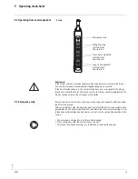
Page 15: ...ve a means of disconnecting the power supply to all drives under load from the ground After an emergency stop the operator must not restart the hoist crane system until a qualified person has determined that the fault which led to this function being activa ted has been eliminated and no danger can arise from the continued operation of the system The emergency stop button is on the control pendant...

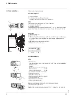
Page 16: ...st be fitted Check load chain for wear see page 17 6 2 3 Every three months Check hook for wear see page 17 Check hook attachment Grease output pinion and open step of gearing on electric trolley Check attachment of rigid suspension or trolley suspension Clean and lubricate chain Check chain attachment 2 1 suspension bolt 6 2 4 Every year Check screw connections tightening torques corrosion Adjust...

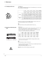
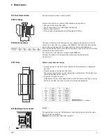
Page 17: ...e load chain above all at the joints Check chain guide chain sprocket and idler sheave on the bottom hook block and replace if necessary see page 22 Check chain anchorage replace if necessary Caution Do not turn and refit a used chain suspension bolt ST05 ST10 ST20 ST30 ST32 ST50 ST60 1 1 2 1 1 1 2 1 1 1 2 1 1 1 2 1 1 1 2 1 1 1 2 1 mm mm mm mm mm mm Load hook h 19 24 19 24 24 31 31 37 31 40 37 48 ...

Page 18: ...ay crane runway suspensions right up to the roof of the buil ding etc can support the increased load on the chain hoist Due to the polygon effect oscillations and tolerances of the friction linings in accor dance with FEM adjustment values between min 110 and max 160 of nominal load are permissible for chain hoists If necessary take the chain hoist down and carry out adjustment on a test stand The...

Page 19: ...BAST_02 FM 19 6 Maintenance ST05 ST10 ST 20 ST 30 ST32 ST50 ST60 09 07 ...

Page 20: ...air gap S If the max permissible air gap S has been reached the brake must be replaced Clean brake wear a dust protection mask Check friction surfaces for wear 6 8 2 Adjusting brake ST05 Set load down Calculate number of shims to be removed The brake displacement is altered by 0 5 mm per shim Example Brake displacement measured 0 8 mm Remove 2 shims 1 0 mm New brake displacement 0 8 mm Lever off c...

Page 21: ... in accordance with FEM 9 671 Components which are in the power flux may only be overhauled by the manufacturer 6 12Trolley Wheels wheel drive and runway Visual inspection of wheels for wear Replace if original diameter is reduced by max 5 Visual inspection of runway beam for wear The running characteristics can be improved by a guide system This avoids wear and the flange play can be reduced Insp...

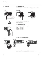
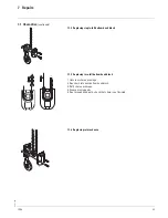
Page 22: ...ng chain stopper Min projecting chain length X of free chain end ST05 X 130 mm ST10 ST30 X 100 mm ST32 ST60 X 150 mm 7 1 3 Checking and fitting chain anchorage Secure chain suspension bolt 1 with lock 2 Replace chain suspension bolt if any grooves or distortion are visible Caution Do not turn over and refit a used chain suspension bolt ST05 ST10 ST60 The welds of the upright chain links must point...

Page 23: ...le fall bottom hook block 7 1 5 Replacing two fall bottom hook block 1 Unscrew chain anchorage 2 Run chain into new bottom hook block 3 Refit chain anchorage 4 Grease moving parts 5 Run through hook path check that chain is not twisted 7 1 6 Replacing return sheave 10 06 ...

Page 24: ...20 10 64 0 E32 16 320 40 64 0 E32 16 320 40 64 0 6 Chain box 32 320 00 26 0 32 320 03 20 0 2 12m 35 322 04 32 0 25m 33 320 26 26 0 8m 35 32204 32 0 16m 33 320 26 26 0 6m 35 320 04 32 0 10m 33 32026 26 0 6m 17 320 00 32 0 20 m 18 322 00 32 0 8m 18 320 00 26 0 12m 18 322 00 32 0 8m 18 320 00 26 0 12m 18 322 00 32 0 7 Suspen sion bolt 32 322 10 92 0 8 Suspen sion bolt 14 320 00 24 0 16 320 00 24 0 13...

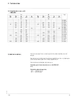
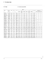
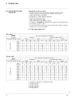
Page 25: ...bient temperatures 20 C 40 C operation 20 C 60 C storage 1 1 2 1 Type 1Bm M3 1Am M4 2m M5 3m M6 4m M7 1Bm M3 1Am M4 2m M5 3m M6 4m M7 kg kg 125 ST 0501 8 125 100 ST 0501 16 250 200 160 500 400 320 ST 0502 8 320 250 200 160 630 500 400 320 ST 0503 6 400 320 250 800 630 500 ST 1004 16 500 400 320 1000 800 630 ST 1005 630 1250 ST 2006 12 800 630 ST 2008 16 1000 800 2000 1600 ST 2010 8 1000 800 630 20...

Page 26: ...120 240 360 120 240 300 120 240 6 3 6 8 3 7 6 3 6 8 3 7 9 0 9 9 5 2 3 6 3 9 2 1 3 6 3 9 2 1 5 7 5 7 3 0 2 9 3 1 1 7 2 9 3 1 1 7 4 6 4 6 2 4 28 9 25 6 7 3 28 9 25 6 7 3 55 7 42 6 10 6 16 6 14 7 4 2 16 6 14 7 4 2 24 5 24 5 6 1 13 3 11 8 3 4 13 3 11 8 3 4 19 6 19 6 4 9 0 82 0 92 0 80 0 82 0 92 0 80 0 90 0 90 0 79 16 10 16 10 20 16 10 6 10 6 10 10 6 6 6 6 10 10 ST 3016 8 ST 3016 8 2E32 2 8E32 2 3 2 3 ...

Page 27: ...3 11 8 3 4 13 3 11 8 3 4 25 6 19 6 4 9 0 82 0 92 0 80 0 82 0 92 0 80 0 90 0 90 0 79 10 10 10 10 10 10 10 6 10 6 10 10 6 6 6 6 10 10 ST 3016 8 ST 3016 8 2E32 2 8E32 2 8 2 8 0 68 60 40 20 360 120 240 6 6 6 6 3 5 5 7 5 7 3 0 4 1 4 6 2 4 28 2 28 2 7 0 24 5 24 5 6 1 25 6 19 6 4 9 0 90 0 90 0 79 10 10 10 10 10 10 ST 3212 16 ST 3212 16 4 ST 3216 8 ST 3216 8 2 ST 3216 12 ST 3216 12 3 2E42 2 8E42 2E40 2 8E...

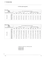
Page 28: ...400 V 500 V 230 V 400 V 500 V 230 V 400 V 500 V 230 V 400 V 500 V Hoist motor type 2A04 2 8A04 57 170 269 94 283 29 80 120 49 2E21 8 2E21 17 18 50 55 79 87 28 31 84 92 131 144 10 11 30 33 47 52 17 18 50 55 79 87 2E22 8 2E22 13 14 38 42 60 65 21 23 64 70 99 109 8 8 23 25 36 39 13 14 38 42 60 65 2E31 8 2E31 11 11 34 34 53 53 19 19 57 57 89 89 7 7 21 21 32 32 11 11 34 34 53 53 Contactor control 50 Hz...

Page 29: ...0 66 66 6 6 18 18 24 24 10 10 30 30 40 40 Contactor control 60 Hz Max cable length with contactor control m Chain hoist Stationary 3 With trolley along runway 4 Connecting cable cross section 1 5 mm 2 5 mm 1 5 mm 2 5 mm 400 V 460 V 575 V 400 V 460 V 575 V 400 V 460 V 575 V 400 V 460 V 575 V Hoist motor type 2A04 8 2A04 113 340 531 71 214 334 118 2E21 8 2E21 36 40 109 122 170 190 60 67 181 203 283 ...

Page 30: ...ala Oil 460 Texaco Meropa 460 2 Viscosity 460 cSt 40 C pour point 40 C flash point 320 C e g Shell Tivela Oil WB 3 Soap base natron dripping point approx 150 C penetration 400 430 operating temperature 30 C to 80 C e g Aralub PDP 00 BP Energrease HT 00 EP ESSO Liquid Gear Grease 4 Soap base Li polyglycol oil dripping point approx 180 C penetration 400 430 operating temperature down to 40 C e g Ess...

Page 31: ... Outdoors 9 8 Chain certificate 1 Tractive force on chain 2 Test load 3 Minimum breaking load Typ dB A ST05 ST 60 74 Travel drive type db A 3 h m 1 m 2 m 4 m 8 m 16 m SU A 78 75 72 69 66 SF 2 72 69 66 66 63 SF 8 78 75 72 69 66 Travel drive type db A 3 h m 1 m 2 m 4 m 8 m 16 m SU A 78 72 66 60 54 SF 2 72 66 60 54 48 SF 8 78 72 66 60 54 W0923 Order No 1 1 2 1 mm kg kN kN 3 m ST 05 ST 10 ST 20 ST 30 ...

Page 32: ...1 44471 69 ferrometal ferrometal pt Spain Madrid 34 91 484 0865 34 91 490 5143 info stahlcranes es Switzerland Frick 41 62 82513 80 41 62 82513 81 info stahlcranes ch America Asia T F E China Shanghai 86 21 6257 2211 86 21 6254 1907 victor low stahlcranes cn India Chennai 91 44 4352 3955 91 44 4352 3957 anand stahlcranes in Singapore Singapore 65 6271 2220 65 6377 1555 sales stahlcranes sg U A E D...

Reviews: