BAST_
02.FM
12
3 Installation
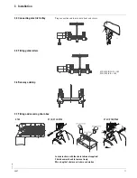
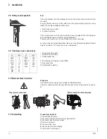
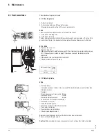
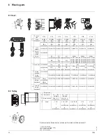
3.8 Fitting control pendant
N.B.:
The control pendant must be suspended from from the strain relief wire and not from
the cable!
Ensure sufficient clearance of the cable to the chain by turning the plug if necessary
(±360°)! The cable must
not
touch the chain.
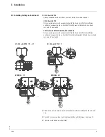
1. Plug in and secure cable.
2. Fit strain relief wire.
If the customer connects the control cable by means of a plug kit, the circuit diagram
must be followed (parts marked "A" are supplied loose).
Prepare ends of cable acc. to sketch "Mains connection, plug-type".
For connecting control pendant without plug, see circuit diagram supplied. (Terminal
strip X1, terminals 1...9. Connection is via a cable gland.)
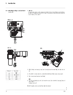
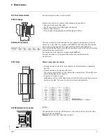
3.9 Checking screw connections
• Chain guide attachment
• Distance bolt on trolley
• Trolley suspension
*1 Self-locking/self-tapping screws (ST05)
*2 Plug connection
*3 Cable gland (in plastic)
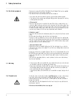
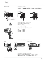
3.10 Netzanschluss herstellen
Safety note
The chain hoist may only be connected by a skilled electrician.
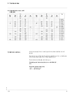
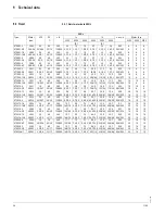
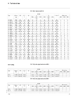
The mains cable must meet the specifications given in the technical data, see page
28.
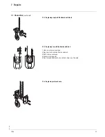
3.11 Dismantling
Dismantling chain hoist
1. Remove load from hoist
2. Disconnect chain hoist from mains at main isolator
3. Disconnect electrical connections
4. Remove chain hoist
5. Remove trolley, if any
6. Clean chain hoist and oil lightly
7. Seal air vent screw in gear.
M..
[Nm]
M..
[Nm]
M5
M5*1
M5*2
M5*3
M6
M8
M8*1
M10
M12
6
5
1,0
1,5
10
24
15
48
83
M16
M20
M20x1,5
M24
M30
M36
120
300
300
320
640
1100
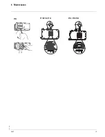
Mains connection with cable gland
Plug-in mains connection
1
2
3
09.07


