Operating Instructions ET-xx8 / MT-xx8
Appendix B
Page 58 of 84
R. STAHL HMI Systems GmbH / OI_ET_MT-xx8_en_V_01_02_03.docx / 10.03.2021
18 Appendix B
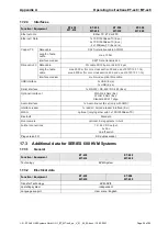
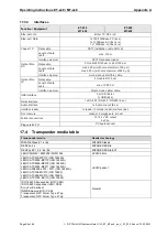
18.1 Connection values
Nominal
voltage
Input voltage range
Rated
frequency
max. power
consumption
100
– 240 VAC
85
– 250 VAC
50
– 60 Hz
5 A (with heater on)
24 V DC
20
– 30 VDC
–
8 A (with heater on)
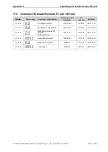
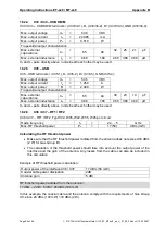
18.2 Intrinsically safe interfaces (Ex ia)
For field wiring refer to Control Drawing 11100025 Taken together with this document, the Control
Drawing contains information on the connection and the electric parameters.
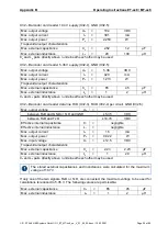
18.2.1
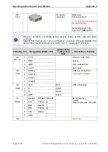
X30 PB
– on/off switch
X30: PB, on/off switch (X30-1, X30-2) parallel wiring, GND (X30-3, X30-4):
Max. output voltage
U
o
=
5.36
VDC
Max. output current
I
o
=
46
mA
Max. output power
P
o
=
0.061
W
Trapezoidal output characteristics
Max. external capacitance
C
o
=
65
10
µF
Max. external inductance
L
o
=
1
20
µH
C
o
and L
o
pairs directly above / underneath each other may be used.
18.2.2
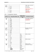
X31 - Fan
X31 Fan power (X31-1), (X31-3) per circuit, GND (X31-2, X31-4):
Max. output voltage
U
o
=
15.75
VDC
Max. output current
I
o
=
189
mA
Max. output power
P
o
=
1.092
W
Trapezoidal output characteristics
Max. external capacitance
C
o
=
0.29
0.478
µF
Max. external inductance
L
o
=
100
20
µH
C
o
and L
o
pairs directly above / underneath each other may be used.
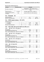
18.2.3
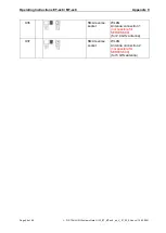
X32
– Barcode / card reader
Devices connected to X32 may be connected to the supply circuit via: 10.4 V (X32-1) or
5.36 V (X32-2).
Terminals 1 and 2 may not be used simultaneously.
Terminal block X32 contains a joint terminal (X32-5) for the GND of the supply and data
line.
If the connection cable of the connected device uses only a joint GND line, the joint current
must be taken into account when determining external inductances.


