Page | 16
2.9 Parallel UPS Systems
Parallel Operation requires a factory installed Paralleling Kit. (SCV-PAR-10)
At the rear of the unit; if plastic covers over (2) DB9 holes then the kit is NOT installed.
See
Figure 19:
UPS Parallel Communication ports
2.9.1 Calibration
Verify items below before powering up the parallel system, in order to make sure UPS module parallel
properly.
1.
Make sure that the parallel board and OP relay board have been installed.
2.
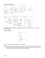
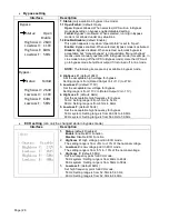
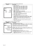
Make sure that each UPS has the same configuration (See
a) output voltage,
b) output frequency,
c) bypass voltage range,
d) bypass frequency range,
e) converter enable or disable,
f)
bypass enable or disable,
g) bypass open or forbidden,
h) frequency auto detect enable or disable,
i)
inverter short clear enable or disable
3.
Turn on each UPS into the line mode or battery mode respectively (see
utility power supply (to Line mode)
). Measure and calibrate the output voltage with a multimeter.
Make sure the difference of the output voltage among the UPSs is less than 2.0V (typical 1V). If not,
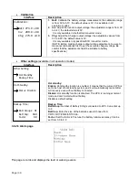
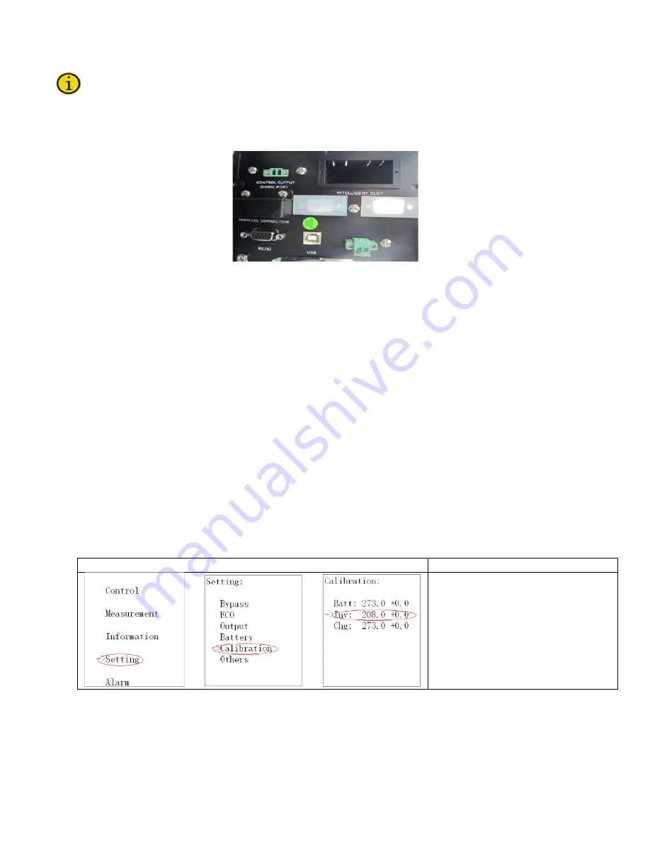
you can adjust the voltage via LCD as below (See
).
Interface
Setting
->
- >
You can choose
Add
or
Sub
to
adjust inverter voltage. And the
voltage range is from 0V to 9.9V,
the default value is 0V.
4.
After adjusting the inverter voltage, check if the output voltage detection is ok. If the difference
between the displayed value and the voltage measured by a multimeter is more than 1V, please
adjust it to make sure the difference is less than 1V. Then, shut down the UPS to save this setting
into EEPROM.


