background image


28


3.5.5.3  Except Buzzer (as drawing Q1 & Q2)  and Self-test(as drawings R1 & 

R2), all the rest default settings may be  changed by pr essing scroll up 

 ke y pad. 

3.5.5.4  Drawings S1 and S2 mean the bypass input acceptable window, it  can 

be 184Vac~260Vac or 195Vac~260Vac. 

3.5.5.5  Drawing T means the bypass frequency window of the Inverter Output, 

the acceptable setting values are ±3Hz and ±1Hz. 

3.5.5.6  Drawing U  me ans the  ac ceptable Inve rter Ou tput  Voltage,  of  which 

voltage is 200Vac, 208Vac, 220Vac, 230Vac, or 240Vac. 

3.5.5.7  Drawing V1, V2,  V3 and V4 mean the operation modes of the UPS, of 

which alternative is Online, Eco(Economic) mode, fixed 50Hz Output or 

fixed 60Hz Output. 

3.5.5.8  Drawing W means the adjustments of the Inverter Output, which may 

be calibrated as 0%, +1%, -1%, +2%, -2%, +3%, or -3%. 

3.5.5.9  Drawing X means a specified address & position of the UPS when the 

UPS is in Parallel mode. The settable numbers are from 1st to 4th.   

3.5.5.10  Drawing Y means the total numbers of the UPS in parallel. The settable 

numbers are from 1 to 4.   

 
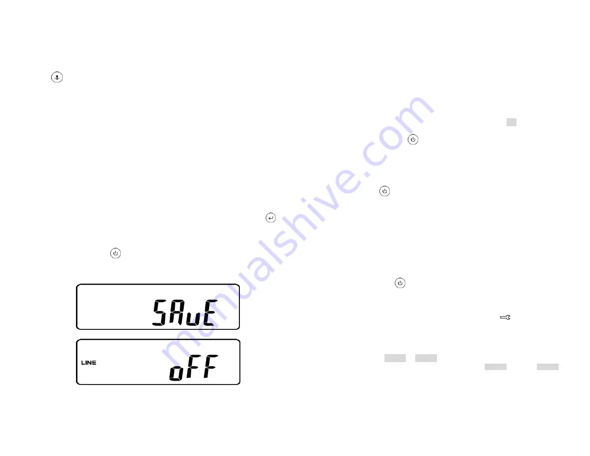
3.5.5.11  When  all th e s etting  changes a re  done, yo u  have to  p ress  enter 


key  Pad  to  save all t he  changes  when  the LCD scre en  shows as 

drawing Z, then, the LCD screen will show as drawing AA  to complete 

the  setting c hanges.  If yo u d on’t w ant to  c hange th ose s ettings,  you 
may pre ss  “OFF” 

  key pa ds fo r 5 seco nds, t hen th e LC D  screen 

turns  to  Drawing AA   directly, wh ich me ans  your se tting cha nges ar e 

invalid. 


  * Please press Enter key to save data. 


AA 


* It shows the UPS is locked.   


29


3.5.5.12  Turn Off the breaker of Utility Input. 

3.5.5.13  Your Setting changes are complete. 


3.5.6 

  UPS Is Off Due to Unknown Reason and Its Trouble Shooting 

3.5.6.1  If there  is a  serious abnormal conditi on occu rred, the UP S will  lock  it 

itself  in  “OFF”  position  as  shown i n d rawing A A  and a  ab normal 

message will show in the LCD screen. 


3.5.6.2  To release the UPS lock, please proceed the followings: Check those 

error  messages  recorded. C heck  to s ee Ch apter 2 .2 to  tr ouble s hoot 

the  problem  of  the  UPS. O therwise, co nsult y our l ocal d istributor  for 
service. P ress Off  

  key pa d f or 5   seconds an d bu zzer will   sound 

twice. Turn  Off  the B reaker of Utility  Input. The  UPS lock problem   is 

solved n ow, b ut y ou sh all co ntact  with  your Lo cal dist ributor  to  make 

sure the error message shown is solved. 

3.5.7 

Shut Off   


3.5.7.1 Pr ess Off 

  key pad for about 5 seco nds, the Inverter output will be 

turned off, then the output load is supplied by Bypass loop and the LCD 

screen shows as drawing B. 

3.5.7.2  Turn Off the breaker of Utility Input. 

3.5.7.3  The UPS is turned off completely. 


3.5.8 

Maintenance Bypass Mode   


3.5.8.1  It  is  for  UPS ma intenance o nly. A  No n-authorized t echnician is n ot 

allowed  to  operate  the  following pr ocedures. I f t here is an y  damage 

under unauthorized condition, your warranty will be void immediately. 

3.5.8.1.1 P ress the Off 

  key pad for approx. 5 seconds, the LCD screen 

shows as drawing B and the UPS output is on bypass mode. 

3.5.8.1.2  Release the cover of the CAM Switch (Maintenance Bypass Switch) 

first, then turn on the CAM Switch to “Bypass” mode, and at the right-

hand upper Corner of the LCD screen will show 

 sign . 

3.5.8.1.3  Turn off the UPS Utility breaker, you then may proceed UPS 

maintenance now. 

3.5.8.1.4  To repeat 3.5.1.4, you may put the UPS back to normal working mode, 

then turn back the CAM switch to “INV” mode, fasten back the cover 

and repeat 3.5.1.5 to 3.5.1.9 The UPS will switch back to inverter mode. 

3.5.9 

It is required to go through 3.5.8.1.1 first, then go th rough 3.5.8.1.2 If y ou skip 3.5.8.1.1, the 

UPS will alert for 10 seconds to warn that the procedure is abnormal, which may damage the 

UPS due to uncertain utility status. The UPS w ill switch back to Inverter mode immediately if 

you turn the CAM switch back to “INV”. 

Summary of Contents for SC60021RM

Page 1: ...king 11 3 2 Selecting Installation Position 12 3 3 Installation of Casters Cover 13 3 4 Terminal Block Explanation 18 3 5 Operation Test and Installation Instruction 19 4 Troubleshooting Guide 30 4 1...

Page 2: ...ntrol medical and security applications Non authorized technician is not allowed to install the UPS in the following areas a Medical equipment directly related to human life b Elevator Metro Subway sy...

Page 3: ...condition ceases 2 1 5 Should t he output becomes sho rt circuit th e U PS ho lds th e system and cuts the output automatically till the short circuit situation is removed manually 2 1 6 Should the un...

Page 4: ...tem desired to be measured 14 UPS ON Switch or Alarm Silence 15 UPS OFF Switch 16 Previous Page or Setting Change 7 17 Next Page 18 Special Function Log in out 19 Enter or Reconfirmed 20 Utility Input...

Page 5: ...working under ECO Economic Line interactive mode UPS Fault or Abnormal UPS ON Alarm Silence UP S OFF Switch Sp ecial functions log in out Go to next page Go to previous page or change the setting of...

Page 6: ...ll get the highest priority in control command then the SNMP WEB card then R2E RSE and USE get the lowest priority 2 4 1 True RS232 type 2 4 1 1 The RS232 interface settings The RS232 interface shall...

Page 7: ...r flow to the ventilation openings of the unit 3 Please check the installation site to avoid overheat and excessive moisture 4 Do not place the UPS in an environment near dust corruptive or salty mate...

Page 8: ...installation step 3 3 2 1 Power Module Battery Module Step 1 Installation Power Isolation Transformer and Battery Step 1 Installation Ear Cover S3 B1 B2 S4 B1 B3 S4 15 Step 2 Installation Ear Cover to...

Page 9: ...3 3 2 2 Power Module Isolation Transformer Module Battery Module Step 4 Installation Battery Module to Step 1 Installation Isolation Transformer Module to Rail 17 Step 2 Installation Power Module to R...

Page 10: ...SET OUTPUT BREAKER PUSH TO RESET OUTPUT 20A MAX OUTPUT 30A MAX 20AMAX 15A MAX OUTPUT BREAKER PUSH TO RESET 15A MAX 30A 20A 19 3 5 Operation Test and Installation Instruction 3 5 1 Start Up in Normal M...

Page 11: ...charged 3 5 2 Start up in Battery Mode Cold Start 3 5 2 1 Make sure the UPS you have has already been installed at least 1 set 20pcs of 12V 7AH or 12V 5AH batteries 3 5 2 2 Push the UPS On Switch to a...

Page 12: ...s Input Drawi ng J Frequency from Utility Input Drawing K Frequency fr om B ypass I nput Drawing L UPS Ou tput Vo ltage Drawing M UPS Output Frequency Drawing N UPS Output Load Drawing O UPS Battery V...

Page 13: ...ween Drawing Q1 buzzer Drawing R1 Self test Drawing S1 Bypass Voltage Windows D rawing T O utput Fre quency Synchronization Window Drawing U Inverter Output Voltage Drawing V1 UPS Operation Mode Drawi...

Page 14: ...scroll up key pad you may execute special functions The Functions i ncludes bu zzer ON a s dra wing Q1 or buzzer OFF as drawing Q2 Alarm silence for UP S W arning an d se lf test OFF As drawing R1 or...

Page 15: ...ng A A and a ab normal message will show in the LCD screen 3 5 6 2 To release the UPS lock please proceed the followings Check those error messages recorded C heck to s ee Ch apter 2 2 to tr ouble s h...

Page 16: ...erwise consult your local distributor right away 2 Remove some uncritical load at the UPS output end If any damage of the coating of AC power cord please replace a new one 3 Remove the short circuit o...

Page 17: ...gnments of the EPO are 1 EPO 2 Ground 6 1 1 To enable the EPO function please short Pin 1 2 6 2 R2E 2nd RS 232 card 6 2 1 CN1 is for RS232 DB9 and CN3 is for EPO 6 2 2 For communication protocol pleas...

Page 18: ...shutdown function please short Pin 8 10 6 5 4 Adapted flat cable cable A or cable B 6 5 5 For installation please refer to Chapter 6 7 1 VCC 5V 2 D 3 D 4 Ground 35 6 6 SNMP Cards 6 6 1 SNMP WEB card...

Page 19: ...1 Unscrew the flank of the battery bank front panel as indicated in Step 1 2 Remove the front panel as indicated in Step 2 3 Remove the screw of the battery pack as shown in Step 3 4 Unplug the hot s...

Page 20: ...l Load DC Start Yes Cooling Variable Speed Fans load determines speed DISPLAY ALARMS DIAGNOSTICS COMMUNICATIONS Status On LED LCD Line Mode Backup Mode ECO Mode Bypass Supply Battery Low Battery Bad D...

Page 21: ...of installation max 42 months from ship date for UniStar III and two 2 year from date of installation max 30 months from ship date for UniStar III P Please read your Warranty carefully This Warranty...

Page 22: ...nd supersede all previous warranties Staco reserves the right to supplement or change the terms of this Warranty in any subsequent warranty offering to User or others In the event that any provision o...

Reviews: