Board architecture
UM0522
14/39
7 Board
architecture
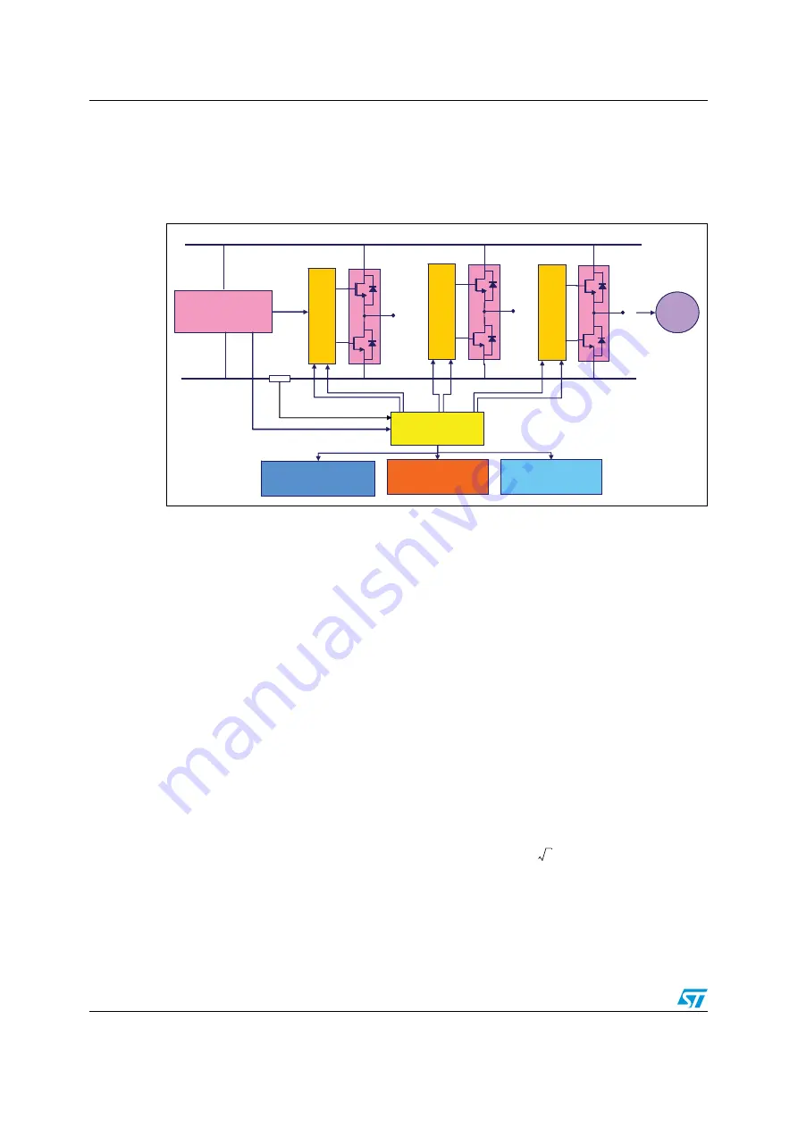
The STEVAL-IHM017V1 can be schematized as in
Figure 4.
Board architecture
The heart of the evaluation board is the ST7MC microcontroller with a dedicated peripheral
included to drive the three-phase brushless motor with permanent magnet rotor exploiting
trapezoidal sensorless control. The board is provided with three potentiometers (R61, R62,
R63) used for tuning, in real time, some parameters related to the drive. See
Motor control operations on page 19
Two LEDs (green/red) are used to get information about the status of the system. Their
behavior is related to the drive. See
Section 8: Motor control operations on page 19
In normal functionality it is expected that the board is supplied by VBUS connector J9 but an
auxiliary supply connector CON2 is included on the board to feed the drivers and the
microcontroller. This auxiliary supply can be useful for safety reasons, for example it should
be used to program or debug the device without feeding the board with high voltage.
One communication system can be established with the microcontroller:
●
ICC used for programming/debugging purposes
7.1 Power
supply
The power supply is able to address a wide range of AC input voltage voltages from 30 Vac
up to 270 Vac. The alternate current input is rectified by a diodes bridge and bulk capacitor
to generate a direct current bus voltage approximately equal to Vac minus the voltage
drop on the bridge and ripple.
Then we have used a VIPer12A-E based buck converter to generate voltage reference for
driver 15 V and a linear voltage regulator L7805 to generate the microcontroller voltage
reference (see
).
ST7MC
ST7MC
Power
Supply
Power
Supply
PWMs
ICC
ICC
LEDs
LEDs
5V
Potentiometers
and button
Potentiometers
and button
V Bus
M
M
L6386L6386
L6386L6386
L6386L6386
Vdriver
R
SENSE
2
www.BDTIC.com/ST


