background image

3

020-053-UK R2

BoomPilot

®

installing thE tJ744 aBsC kit

Connect the automatic boom section kit as shown on the system overview diagram, 
Figure 1-1. The kit includes all necessary connectors to get electrical contact with the 
TJ744E system.

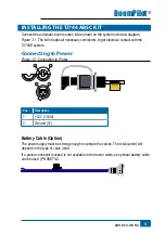
Connecting to power

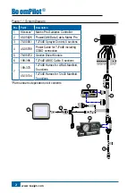
Figure 1-2: Connecting to Power

+ -

1

1

2

2

1008-0189

15/

30

82

31

Pos.

Description

1

+12V (15/30)

2

Ground (31)

Battery Cable (Option)

The power supply must be strong enough to operate the valves. The total current will 

depend on the type of valve used.
If a power connector (socket) is not available in the tractor cabin, an optional battery cable 

can be used (PN 96ET14).

Summary of Contents for TeeJet TECHNOLOGIES BoomPilot

Page 1: ...B O O M p i lot Install ation Manual Automatic Boom Section Control for TJ744E with 5 sections and Matrix Pro...

Page 2: ...OSS OF USE OR DATA INTERRUPTION OF BUSINESS OR FOR INDIRECT SPECIAL INCIDENTAL OR CONSEQUENTIAL DAMAGES OF ANY KIND EVEN IF TEEJET TECHNOLOGIES HAS BEEN ADVISED OF SUCH DAMAGES ARISING FROM TEEJET TEC...

Page 3: ...Power 3 Battery Cable Option 3 Mount Connect SDM 4 Power CAN Data Cable to BoomPilot Harness 4 system check 5 Check AUTO mode 5 TJ744E Switch box 5 Matrix Pro 5 Check MANUAL mode 5 TJ744E Switch Box 5...

Page 4: ...lowing Disturbance to from any electronic services or products that do not confirm to the standards for CE marking Missing or poor signal coverage or a succession hereof from external transmitters rec...

Page 5: ...the section valves in automatic mode The section switches should be set to off unless the operator wants to override the auto mode and thus force spraying The Matrix Pro monitors the section switches...

Page 6: ...Guidance Controller 2 45 05626 Power CAN Data Cable Matrix Pro 3 75 50061 TJ744E Sprayer Control 5 sections 4 45 05789 Power Cable for TJ744E including COBO connection 5 78 05072 Section Driver Modul...

Page 7: ...contact with the TJ744E system Connecting to Power Figure 1 2 Connecting to Power 1 1 2 2 1008 0189 15 30 82 31 Pos Description 1 12V 15 30 2 Ground 31 Battery Cable Option The power supply must be s...

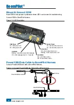
Page 8: ...high or on Blinking boom output is low or off Auto Mode On auto mode is active Off manual mode is active CAN Data Blinking receiving console CAN messages Off CAN messages stop for 3 seconds CAN Power...

Page 9: ...e 2 0 km h 0 76 ha Mark A A A Matrix Pro Turn on the Matrix Pro console Encode the number of sections and the width of each Refer to the Matrix Pro user manual Wait for GPS signal Set the BoomPilot mo...

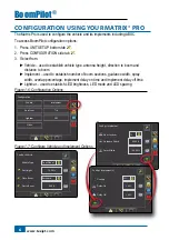
Page 10: ...number of boom sections guidance width spray width overlap percentage implement delay on time and implement delay off time Lightbar used to establish LED brightness LED mode and LED spacing Figure 1 6...

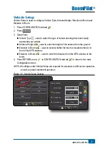
Page 11: ...o Boom used to select whether the boom is located behind or in front of the GPS antenna Distance to Boom used to enter the distance from the GPS antenna to the boom 4 Press RETURN arrow or CONFIGURATI...

Page 12: ...e Width used to enter the width between the guidelines Spray Width used to enter the width of each implement section Overlap used to select the amount of overlap allowed when the boom sections are tur...

Page 13: ...e On Off Manual Mode On On Off Manual Automatic To switch BoomPilot between off manual and automatic 1 Turn the controller master switch to the On position The individual boom section switches should...

Page 14: ...automatic mode on BoomPilot iii turn master On iv begin operation for remainder of field performing guidance functions as desired Figure 1 10 Automatic to All Booms On Mode 0 0 mph 0 00 ac Mark A A A...

Page 15: ......

Page 16: ...k Tel 45 96962500 Fax 45 96962501 www teejet com B O O M p i lot Installation Manual This installation manual covers installation of Matrix Pro with TeeJet 744E Sprayer Control with 5 sections 020 053...

Reviews: