background image

MATRIX

®

 430VF

JOB D

AT

A

CONFIGUR

ATION

INTR

ODUC

TION

CONSOLE

12

www.teejet.com

GUID

ANCE

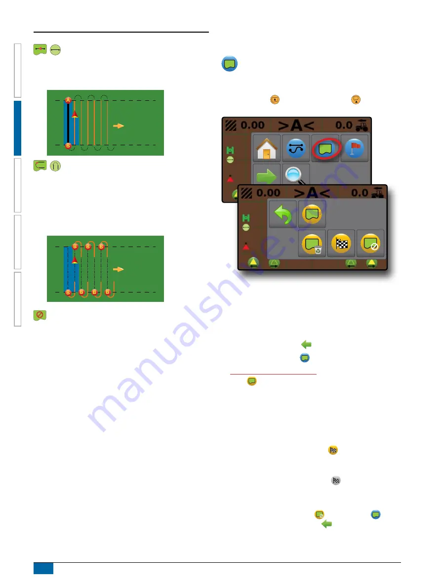
Straight AB guidance

Straight AB guidance provides straight line guidance based on 

A and B reference points. The original A and B point are used to 

calculate all other parallel guidelines.

Next Guideline guidance

Next Guideline guidance indicates where the next guideline is 

located, and provides guidance at the end of a swath path to the 

next adjacent guideline. When the operator marks the end of 

the swath and begins turning to the next guideline, a Straight AB 

guidance line is provided in the next swath path. When the vehicle 

is in the Next Guideline swath path, guidance is turned off.

No guidance

No guidance turns off guidance.

NOTE:  No guidance mode does not delete an established 

guideline or point from the console. To delete established/

saved data from the console, please refer to the Job Data 

chapter.

Application Boundary

Application boundaries establish areas where application is 

and is not to be applied. Boundaries can be established in 

all guidance modes. One exterior boundary can be stored at a 

time. In correspondence to your current location, the IN 

BOUNDARY icon   or OUT BOUNDARY icon 

 is displayed 

on the status bar once the boundary is established.

Creating a Boundary

To establish an application boundary:
1. 

Drive to a desired location at the perimeter of the field/

application area.

2. 

On vehicle view guidance screen, press NAVIGATION AND 

GUIDANCE OPTIONS tab 

 to display navigation options.

3. 

Press BOUNDARY button 

.

4.  

While the vehicle is in motion,

 press BOUNDARY 


button  .

5. 

Travel the perimeter of the field/area.

6. Finish boundary:


X

Travel to within one working width of the starting point. The 

boundary will close automatically (the white boundary line will 

turn dark grey)


X

Press BOUNDARY FINISH button 

. A straight line will 

complete the boundary between your current location and the 

starting point

NOTE:  The BOUNDARY FINISH button   is not available 

for selection (greyed out) until the minimum distance is 

travelled (five-times the working width).

Use CANCEL BOUNDARY button 

 under Boundary   on 

the Navigation and guidance options 

 menu to cancel the new 

field boundary process and revert to the previous boundary (when 

established).

Summary of Contents for TeeJet MATRIX 430VF

Page 1: ...U S E R M A N U A L MATRIX 430VF Guidance for Vineyards and Orchards Software version 1 04...

Page 2: ...propelled Harvester XSet Number of Implement Sections C used to select the number of implement sections Range is 1 to 12 sections XSet Section Widths D used to enter the width of each section Each sec...

Page 3: ...e guidance back to the established point XA Nudge Feature allows the current guideline to be shifted to the vehicle s current location XSection Control enable disable application mapping To adjust the...

Page 4: ...Components 1 Recommended Antenna Installation 1 POWER 2 BASIC SCREEN USE 2 Home Screen 2 Keyboard Entry Screens 3 Options Menus 3 ICON REFERENCE 3 CHAPTER 2 GUIDANCE 5 GUIDANCE SCREEN OPTIONS AND INFO...

Page 5: ...r programmes described in it may be reproduced copied photocopied translated or reduced in any form or by any means electronic or machine readable recording or otherwise without prior written consent...

Page 6: ...ase contact a local dealer Keep children away from equipment Do not operate machinery under the influence of alcohol or any illegal substance Some systems include a fan heater Never cover the heater o...

Page 7: ...that this apparatus is well aligned and that all connections are tight The plumbing supply to the equipment should meet all company and local regulations and must be properly routed and connected to t...

Page 8: ...s do not hang below the equipment Allow sufficient clearance for harness cables and hoses from implement and machine operational zones When cleaning equipment protect harness cables from high pressure...

Page 9: ...cover Standard RAM Bracket assembly required Bright Touch Screen System Components Connect 12v at 15 30 Connect GND to 31 Power Cable 45 05867 DC xx xx Console Matrix 430VF CG430VF GLO Kit RAM Mount...

Page 10: ...nfiguration or application functions Configuration options can be applied using option menus or keyboard entry screens NOTE When application is active some configuration options are unavailable Home S...

Page 11: ...te option or use a next page arrow to access additional options To close the list without changing the current option select the current option To change a value 1 Press CURRENT VALUE 2 Select an appr...

Page 12: ...lf Propelled Harvester Number of Implement Sections Section Widths In Line Implement Offset Distance Field Configuration Field Profile Number Row Spacing Canopy Width Number of Rows to Next Guideline...

Page 13: ...idance Options Tab Navigation Guidelines On Screen Guidance Guidelines WOrange active guidance line WBlack two guidance lines adjacent to the left and right of the active guideline Field Indicators ca...

Page 14: ...ation Activity Selectable Information Selectable Information Selectable Information 1 On vehicle view guidance screen press current value and select an information button XSpeed displays the current s...

Page 15: ...one guideline is available per job Canopies are illustrated using the configurations set in the current field profile in combination with an established AB guideline If no guideline is established can...

Page 16: ...vided to the next guideline Once the vehicle has entered into the next swath path no guidance or guidelines are shown NOTE Offset to Next Guideline will be calculated using the guidance width see Conf...

Page 17: ...idance No icon no guidance Bounded Area Status Outside Boundary currently traveling outside bounded area Inside Boundary currently traveling inside bounded area No icon no boundary established Applica...

Page 18: ...able on the Guidance screen This tab accesses the menu with the Home button guidance modes and navigation options Vehicle View Navigation and Guidance Options Tab Menu Buttons Home used to access Home...

Page 19: ...ease decrease the area displayed on the screen Close menu used to close the Navigation and guidance options menu Guidance Modes The guidance modes button is used to change the guidance mode To choose...

Page 20: ...s can be established in all guidance modes One exterior boundary can be stored at a time In correspondence to your current location the IN BOUNDARY icon or OUT BOUNDARY icon is displayed on the status...

Page 21: ...Press DELETE BOUNDARY button Return to Point Return to point provides guidance back to an established point An arrow directs the vehicle back to the established point A return point will remain active...

Page 22: ...NCEL RETURN TO POINT GUIDANCE button under Return to point on the Navigation and guidance options menu to hide distance and guidance to the established point Guidance cannot be calculated when appears...

Page 23: ...s bar icon will change to red Mapping with Work On Off Switch When installed the work on off switch should remain in the off position for all setup options To switch mapping and alerts off or on using...

Page 24: ...ne Types section of this chapter for more details Mounted and trailed Airblast Tower nebuliser Powder machine Self propelled Harvester XNumber of Implement Sections used to select the number of implem...

Page 25: ...chine has unique options to indicate how the vehicle will be displayed in relation to the rows and canopy on the Guidance screen Mounted and Trailed Airblast The vehicle is located between rows and do...

Page 26: ...the boom The guideline is centered between rows Self Propelled The vehicle is located between rows with a boom having from 1 to 12 sections The working width is centred on the boom The guideline is c...

Page 27: ...g used to enter the spacing between each row Range is 0 1 to 32 8 feet 0 03 to 10 00 metres XCanopy Width used to enter the width of the canopy Range is 0 1 to 78 7 feet 0 03 to 24 00 metres XNumber o...

Page 28: ...From the Home screen press CONFIGURATION button 2 Press GNSS button 3 Select XGPS uncorrected signals from the GPS system XSBAS e g EGNOS GAGAN MSAS SDCM WAAS adds differentially corrected signals fr...

Page 29: ...ed Area WBounded Area NOTE Bounded area is only shown when a boundary is active WApplication Time 1 From the Home screen press DATA button 2 Press Job Number to view information for a different job WE...

Page 30: ...9 ha 6 9 ha 45 6389 111 3946 www teejet com Matrix 430 2014 TeeJet Technologies Software version 1 01e 1 Memory Notifications The console has a limited amount of storage space to retain job informatio...

Page 31: ...ours on the display XUnits used to define the system measurements XDemonstration Mode used to start playback of simulated GNSS data WGNSS press to use real GNSS signals WDemo press to start demonstrat...

Page 32: ...www teejet com MATRIX 430VF U S E R M A N U A L 98 05351 EN A4 LT R1 English International TeeJet Technologies 2019 GUIDANCE FOR VINEYARDS AND ORCHARDS View Matrix 430VF video at youtube com c teejet...

Reviews: