12
STEP 3
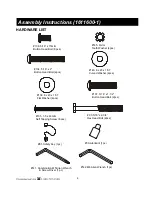
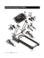
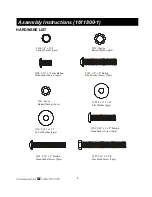
1. Install Handpulse Tube (7) onto the inside of the Left and Right Handrails (4,5) with 4pcs of
5/16” x 1-3/4” Button Head Socket Screws(104) and 4pcs of 8 x 23 x 1.5T Curved Washers
(110 by using the Combination M5 Allen Wrench & Screwdriver (111)(hand tighten only).
Carefully feed the wires on the sides into the center hole in the Handrail and snake them out
of the top of the Handrails (4,5).
2. Install the Handrail Support (3) into the Left and Right Handrails (4,5) with 4pcs of 5/16”
x 15m/m Button Head Socket Screws (102) by using the Combination M5 Allen Wrench &
Screwdriver (111).
3. Tighten all the screws installed in steps 1-3 above.
STEP 4
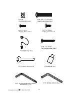
1. Connect the Computer Cable (upper)(31) with Computer Cable (middle)(33).
Connect the Speed Cable (upper)(34) with Speed Adjustment Switch W/Cable (38).
Connect the Incline Cable (upper)(35) with Incline Adjustment Switch W/Cable (39).
Connect the Handpulse Cable (50-1) with Handpulse W/Cable (50).
Connect the receiver w/cable (37-21) with the lower receiver cable (139).
NOTE:
There should be
3
connectors on the right side and
3
connectors on the left side.
2. Put the 4pcs of M5 Iron Plate Nuts (84) onto the sides of the motor cover. There are 2 places
for the Iron Plate Nuts (84) on either side of the motor cover that look like an upside down “U”.
They are located on the small lip on the side of the motor cover. Install the L&R Motor Base
Caps end caps (40,41) with 2pcs of 5 x 16m/m Tapping Screws (92) and 6pcs of 5 x 16m/m
Tapping Screws (87) by using the Combination M5 Allen Wrench & Screwdriver (111).
3. Install the outside pieces of the console end caps with 6pcs of 3.5 x 25m/m Self Tapping
Screws (107) by using the Combination M5 Allen Wrench & Screwdriver (111).
NOTE: Be careful, don’t cut the wires.
4. Attach the Beverage Holder (48) onto the Handrail Support (3).
5. Insert the two bolt access caps (146) into the handgrip side caps (67 / 68, 69 / 70).
ENSURE THAT ALL NUTS AND BOLTS ARE NOW FIRMLY TIGHTEN.


