8
5.5 CAPACITANCE
When measuring resistance always make sure the power to the circuit is off.
1. Insert the black (negative) test lead into the COM input terminal.
2. Insert the red (positive) test lead into the INPUT terminal to the right of the COM terminal.
3. Set the Rotary Switch to *insert capacitance symbol
4. Remove the capacitor from the circuit and ensure that it is properly discharged.
5. Place the red and black test leads at the capacitor terminal to be measured. It will take a few seconds for the capacitance to be displayed.
Note: Because of the stray capacitance of the test leads and the input circuit of the meter, the display may show a reading other than zero
before the test leads are connected to the capacitor to be tested. It is normal and this reading must be subtracted from any subsequent
measurements. Make sure the capacitor to be tested has been discharged thoroughly before measurement. For measurements > 10 uF,
it may take up to 30 seconds for the meter to stabilize.
5.6 TEMPERATURE ˚C ˚F
1. Set the Rotary Switch to °C°F
2. Temperature can be displayed in both Celsius and Fahrenheit units.
Press the “
SELECT” key to switch the unit of temperature being displayed.
3. Insert the K-type Temperature Probe into the meter. The negative (-) side of the probe should be connected to the
COM input and the positive (+) side of the probe should be connected to the INPUT terminal.
4. Contact the sensor (metal tip) of the K-type Temperature Probe to the object being tested.
5. The display will show the temperature measurement being taken.
Note: Never touch the K-type Temperature Probe to an energized circuit.
5.7 NON-CONTACT AC VOLTAGE DETECTION (NCV)
1. Remove the test leads
2. Rotate the dial to the NCV position
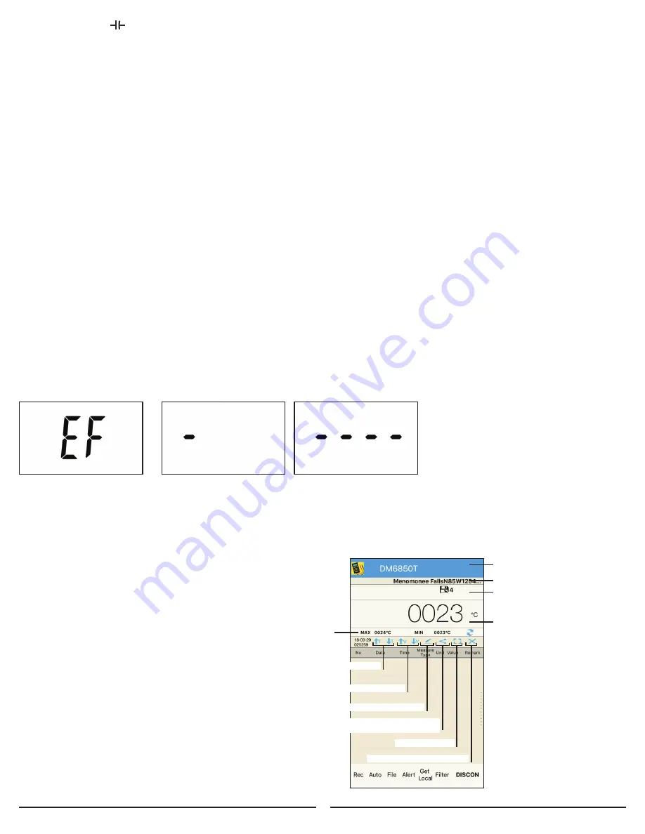
3. The meter will display “EF” when the NCV function is being used (Figure 3)
4. Move the top of the meter close to the object to be tested.
5. When the meter detects AC voltage, the built-in buzzer will beep and the display will indicate the intensity of the detected electric field.
6. The higher the intensity of the detected electric field, the larger the number of the bar graph segments (Figure 4 and 5),
and th faster the beeping rate of the buzzer.
Figure 3
Figure 4
Figure 5
Note: Test on a known live source before use. Even if the meter does not provide indication, potentially hazardous voltage could still be
present (The meter will only detect voltages above 50VAC and only when conditions are correct). The meter can be affected by: Distance
from voltage source, Condition of meter and batteries, Shielded wires, Metal enclosures, Insulation thickness, and Static charge among other
things. The meter is sensitive to electrostatic fields. Occasionally a static charge may interfere with the meter detection and the meter may
omit a tone momentarily.
6.0 SMART DEVICE & APPLICATION
1. The Sperry DM6850T has the ability to be connected
to your smart device via a Bluetooth connection.
2. While the connection is established
the meter will continually transmit data
to your smart device.
3. The measurement data will be shown in the
“Measurement Display Area” of your smart device.
(Figure 6)
Lists currently selected DMM. Tap blue
bar to toggle between meter selections
GPS location
GPS l Current DMM measurement
Datalogging symbol and seconds
active displayed when datalogging
is active of DMM.
Current session
measurement range
Sort measurements by time
Sort measurements by value
Toggle screen view
Save/Erase stored measurements
Pencil symbol for deleting data points
Share symbol for sharing
measurements via email, SMS, etc
Figure 6


