


PCI.212 Manual
31.03.2004
Page 14 of 25
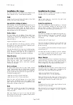
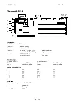
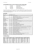
Placement PCI.212
-
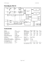
' & FKD QQH O
' LJ LWD O,QS XWV
FKD QQH O
6 \QF% XV
-
' & FKD QQH O
Connectors
The PCI.212 has four 9 mm BNC connectors.
Connector 0:
analogue channel 0.
Connector 1:
analogue channel 1.
Connector 2:
triggermode = TTLPOS or TTLNEG:
external trigger input
triggermode
z
TTLPOS and TTLNeg
trigger output
Connector 3:
EXTERNALCLOCK = 1
clock input
EXTERNALCLOCK = 0
clock output
AC/DC jumper
DC coupling channel 0
DC coupling channel 1
J2 set
channel 0 DC coupled
J6 set
channel 1DC coupled
J2 clear
channel 0 AC coupled
J6 clear
channel 1 AC coupled
Digital inputs PCI.212
Pin 1
D0
Pin 2
GND
Pin 3
D1
Pin 4
GND
Pin 5
D2
Pin 6
GND
Pin 7
D3
Pin 8
GND
Pin 9
D4
Pin 10
GND
Pin 11
D5
Pin 12
GND
Pin 13
D6
Pin 14
GND
Pin 15
D7
Pin 16
GND
Sync Bus
Carries the signals for synchronisation of multiple PCI.212
Pin 1
Sample Clock
Pin 3
Sync Trigger
Pin 5, 6, 8, 10
not used
Pin 2, 4, 7, 9
GND