


PCI.212 Manual
31.03.2004
Page 19 of 25
Command register
The command register executes commands like start and stop or synchronises the board with other boards. If the board is synchronised, it
will not be started.
register name
reg no.
r/w
SPC_COMMAND
0
w
Command register, allowed values listed below.
status code
value
SPC_START
10
Starts the board with the current register settings.
SPC_STOP
20
Stops the board, data in memory is undefined.
SPC_SYNCMASTER
100
Synchronisation with internal Sync bus, this board is master.
SPC_SYNCSLAVE
110
Synchronisation with internal Sync bus, this board is slave.
SPC_NOSYNC
120
No synchronisation.
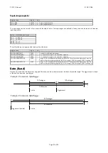
Synchronisation
If two or more boards are synchronised with the internal Sync bus, the boards must be programmed in the following way:
(1)
Set all parameters for all boards including the Sync information.
(2)
Start all slave boards.
(3)
Start the master board.
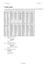
The slave boards must be set to a samplerate related to the master board:
master board
slave board
80.000.000
80.000.000
40.000.000
40.000.000
20.000.000
40.000.000
...
...
100.000
40.000.000
When using external clock for the master board, the samplerate of the slave board should be set to 40 MHz.
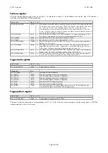
Memory register
This register holds the number of samples, not the number of bytes. The possible values have to be doubled in the interlace mode (80
MHz).
register name
reg no.
r/w
SPC_MEMSIZE
10000
w
memory size for recording: 32 samples up to
installed mem
/2 samples with steps of 32
samples
Posttrigger register
Sets the number of samples to be recorded AFTER the trigger event has been found. The corresponding pretrigger is calculated by the
formula: pretrigger = memsize - posttrigger
If the posttrigger value is higher than the programmed memsize, the trigger event is not visible.
register name
reg no.
r/w
SPC_POSTTRIGGER
10100
w
posttrigger value in the range 32 samples up to 256 MSamples with steps of 32


