background image

PCI.212 Manual

31.03.2004

Page 10 of 25

Installation für Linux

Der Treiber besteht aus einem ladbaren Kernel Modul für alle

Karten. Beispiele für Gnu C werden ebenfalls mitgeliefert.

Installation for Linux

The driver consists of a loadable kernel module for all boards.

Examples for Gnu C are also delivered.

Login

Loggen Sie sich als root ein oder als Benutzer mit dem Recht

Module zu laden und Devices anzulegen.

Auswahl des richtigen Treibers

Die Verwendung von Linux-Kernel-Modulen hängt stark von der

Kernelversion sowie der verwendeten Distribution ab. Diesem

Umstand Rechnung tragend werden die Spectrum Treiber in

verschiedenen Versionen ausgeliefert. Bitte wählen Sie das am

besten passende Archiv für Ihre Installation aus.

Treiber laden

Der Linux Treiber wird als ladbares Kernel Modul spc.o

ausgeliefert. Der Treiber enthält alle Spectrum PCI, CompactPCI

und ISA Karten. Die PCI und CompactPCI Karten werden

automatisch erkannt.

Laden Sie das Modul mit „insmod –f spc.o“.

Der insmod Befehl kann die Warnung generieren, daß das

Kernel Modul für eine andere Kernel Version kompiliert wurde.

Dies Meldung können Sie ignorieren.

Wenn das Kernel-Modul nicht in Ihrere Linux Installation geladen

werden kann, so ist es notwendig den Treiber auf Ihrem System

neu zu kompilieren. Bitte setzen Sie sich mit Spectrum in

Verbindung, um die benötigten Sourcedateien zu bekommen.

Major Number

Für den Zugriff auf den Treiber benötigen Sie die zugeteilte

Major number. Sie finden diese Zahl in /proc/devices. Der

Treiber trägt den Namen „spec“. Normalerweise ist diese

Nummer 254, kann aber auch je nach vorher installierten

Treibern davon abweichen.

Device anlegen

Als letzten Schritt muß ein Device mit dem Treiber verknüpft

werden. Dieses geschieht über den Befehl mknod. Als Major

number wird die in /proc/devices gefunden Zahl eingetragen.

Als Minor Number der Index der Karte die angesprochen wird.

Die Indexzählung beginnt bei 0.

„mknod /dev/spc0 c 254 0“ für die erste Karte

„mknod /dev/spc1 c 254 1“ für die zweite Karte

Stellen Sie sicher, daß alle Benutzer, die mit dem Treiber

arbeiten müssen Schreibrechte für das neu angelegte Device

haben. Dafür können Sie allen Personen Schreibrechte für das

Device erteilen: chmod a+w /dev/spc0.

Ende

Die Karte kann jetzt über das angelegte Device angesprochen

werden. Das genaue Vorgehen kann aus den Beispielen

entnommen werden.

Nach einem Neustart von Linux ist es nur nötig das Treiber

Modul zu laden. Das Device muß nur geändert werden, falls die

Major Number nicht mehr stimmt.

Login

Login as root or login as a user who has the right to load

modules and to install devices.

Select the right driver

Linux kernel modules are heavily depending on the kernel

version and distribution. Therefore the kernel driver for the

Spectrum boards is shipped in different versions. Please select

the archieve that is best matching your installed version.

Load Driver

The linux driver is shipped as the loadable kernel module spc.o.

The driver includes all Spectrum PCI, CompactPCI and ISA

boards. All PCI and CompactPCI boards are recognised

automatically.

Load the module with “insmod –f spc.o”

The insmod command could generate a warning that the driver

module was compiled for an other kernel version. You could

ignore this warning.

It is not possible to use the driver module with linux versions prior

to kernel version 2.0.

If the kernel module could not be loaded in your linux installation

it is necessary to compile the driver directly on your system.

Please contact Spectrum to get the needed source files.

Major Number

For accessing the device driver it is necessary to know the major

number of the driver. This number is listed in /proc/devices. The

device driver is called “spec” in this list. Normally this number is

254 but this depends on the already installed device drivers.

Installing the Device

You connect a device to the driver with the mknod command.

The major number is the number found in /proc/devices. The

minor number is the index of the board starting with 0.

“mknod /dev/spc0 c 254 0” for the first board

“mknod /dev/spc1 c 254 1” for the second board

Make sure that the users that should work with the driver has

write rights to access the device. Therefore you should give all

persons all rights to the device: chmod a+w /dev/spc0

End

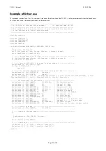
The board could now be accessed using the device. See the

example files for more information.

After restarting linux it is only necessary to load the driver again.

The device must only be changed if the major number has

changed.

Summary of Contents for PCI.212

Page 1: ... x AHRENSFELDER WEG 13 17 x 22927 GROSSHANSDORF x GERMANY TEL 49 0 4102 6956 0 x FAX 49 0 4102 6956 66 x EMAIL info spec de x INTERNET http www spec de 31 03 2004 PCI 212 40 80 MHz 12 bit transient recorder for PCI bus Hardware Manual Driver Manual ...

Page 2: ...marks of Microsoft Corporation LabVIEW is a trademark of National Instruments Corporation MATLAB is a registered trademark of The MathWorks Inc Agilent VEE is a trademark of Agilent FlexPro is a registered trademark of Weisang Co DASYLab is a registered trademark of DATALOG GmbH Spectrum reserves the right to make improvements and or changes to the products and or programs at any time in order to ...

Page 3: ...k diagram PCI 212 13 Technical data 13 Placement PCI 212 14 Connectors 14 AC DC jumper 14 Digital inputs PCI 212 14 Sync Bus 14 Software Description 15 General Information 15 Header files on CD 15 DLLTYP H 15 SPECTRUM H 15 REGS H 15 ERRORS H 15 Driver functions 15 int16 SpcInitPCIBoards int16 count int16 PCIVersion 16 int16 SpcInitBoard int16 nr int16 typ 16 int16 SpcSetParam int16 nr int32 reg in...

Page 4: ...register 19 Features register 20 Triggermode register 20 Triggerpattern register 20 Triggerlevel register 21 Triggeroffset register 21 Samplerate register 21 Input range register 22 Data Read 22 Data format 23 Example of Driver use 24 Transfer speed 25 ...

Page 5: ...ier kann ebenfalls die neueste Treiberverison mit den letzten Fehlerbereinigungen gefunden werden Preface This manual provides detailed information on the hardware features of the PCI 212 from Spectrum Systementwicklung This information includes specifications block diagram connector description In addition this guide takes you through the process of installing your board and also describes the in...

Page 6: ...nvironment Software Kostenlos mitgeliefert werden Treiber für Linux DOS und Windows 9x ME NT 2000 XP Für die einfache Program mierung sind Beispiele in C C Delphi und Visual Basic enthalten Darüber hinaus steht zur komfortablen Steuerung die Signalverarbeitungssoftware SBench 5 2 kostenlos zur Ver fügung Außerdem sind Treiber für LabVIEW DASYLab MATLAB und VEE erhältlich Software Drivers for Linux...

Page 7: ... additional cooling fans it is the best decision to put the board in a slot not adjacent to any other board If you have a system with additional cooling fans place the PCI board in front of a cooling fan 4 Install the board in this slot Make sure that the PCI connector is right struck into the slot 5 Use a screw to fix the bracket to the PC 6 If your board has full PCI length a retainer is deliver...

Page 8: ...nfache Weise in das Programm einzubinden Die Library Datei arbeitet nicht mit Borland Compilern zusammen Die beiden DLL s unterscheiden sich nur im Aufruf der Funktionen Die Datei SPECTRUM DLL exportiert die Funktionen als _cdecl für C C Delphi die Datei SPCSTD95 DLL als _stdcall für Visual Basic Je nach benutztem Compiler kann eine der beiden DLL s benutzt werden Win 98 ME 2000 XP WDM When the op...

Page 9: ...figuriert Bitte überprüfen Sie ob mit dem Programm DRVCONFG EXE ob die Standard Karte PCI Board eingetragen ist Windows NT 1 Login as ADMINISTRATOR or with another account having the right to install drivers and to change the registry 2 Start the setup program on the driver CD The installation program is found in the directory Install WinNTDrv 3 The installation routine will install the kernel mod...

Page 10: ...Sie allen Personen Schreibrechte für das Device erteilen chmod a w dev spc0 Ende Die Karte kann jetzt über das angelegte Device angesprochen werden Das genaue Vorgehen kann aus den Beispielen entnommen werden Nach einem Neustart von Linux ist es nur nötig das Treiber Modul zu laden Das Device muß nur geändert werden falls die Major Number nicht mehr stimmt Login Login as root or login as a user wh...

Page 11: ...D The program supports all actual acquisition generator and digital I O boards from Spectrum Depending on the used board and the software setup one could use SBench as a digital storage oscilloscope a spectrum analyser a logic analyser or simply as a data recording front end Different export and import formats allow the use of SBench together with a variety of other programs An install version of ...

Page 12: ...he converted data to the memory The memory operates as a circular buffer so data are written continuously to the RAM No triggerevents are processed until the programmed memory is filled one time completely with data Afterwards the trigger sequencer will be enabled If Software trigger is used a triggerevent is detected immediately Using the TTL trigger will cause a triggerevent if the external TTL ...

Page 13: ... 40 MHz 10 3 bit typ ADC Crosstalk 40 MHz 64 dB 65 dB 68 dB 69 dB ENOB fs 12 MHz fck 40 MHz 10 0 bit typ ADC Aperture jitter 7 ps rms ADC Dimension PCI 312 mm x 107 mm Input impedance 50 Ohm or 1 MOhm 25 pF Connector 9 mm BNC female Trigger output delay 13 samples Overvoltage protection r20 V Trigger accuracy d40 MHz 80 MHz 1 sample 2 samples Warm up time 10 minutes Ext Trigger to data d 40 MHz 80...

Page 14: ...RNALCLOCK 1 clock input EXTERNALCLOCK 0 clock output AC DC jumper DC coupling channel 0 DC coupling channel 1 J2 set channel 0 DC coupled J6 set channel 1DC coupled J2 clear channel 0 AC coupled J6 clear channel 1 AC coupled Digital inputs PCI 212 Pin 1 D0 Pin 2 GND Pin 3 D1 Pin 4 GND Pin 5 D2 Pin 6 GND Pin 7 D3 Pin 8 GND Pin 9 D4 Pin 10 GND Pin 11 D5 Pin 12 GND Pin 13 D6 Pin 14 GND Pin 15 D7 Pin ...

Page 15: ...lle Register und Kommandos die im Spectrum Treiber für die verschiedenen Karten benutzt werden Die Register die von einer Karte benutzt werden sind weiter unten im kartenspezifischen Teil beschrieben ERRORS H Listet alle möglichen Errorcodes der Funktionen auf Header files on CD DLLTYP H Includes the platform specific definitions for data types and function declarations All data types are based on...

Page 16: ...it integer register to be changed value 32 bit integer value for the register return 16 bit integer error code of function like listed below Sets a register to a defined value or executes a command The board must be initialised before When using ISA boards all installation parameters must be set before address installed memory The allowed registers for the driver are listed in the board specific p...

Page 17: ... board ERR_SEQUENCE 103 259 Channel sequence is not allowed ERR_READABORT 104 260 Data read is not allowed after aborting the data acquisition ERR_NOACCESS 105 261 Access to this register denied No access for user allowed ERR_POWERDOWN 106 262 Not allowed if powerdown mode is activated ERR_CHANNEL 110 272 The channel number may not be accessed on the board Either it is not a valid channel number o...

Page 18: ...ftware driver All constants are found in the header file REGS H PCI register These Registers are set by the driver after PCI initialisation The information is found in the on board ROM The program PCITEST EXE on the driver disk will give the same information s register name reg no r w SPC_PCITYP 2000 r type of board as listed above SPC_PCIVERSION 2010 r board revision high part in bit 8 15 Low par...

Page 19: ...rt all slave boards 3 Start the master board The slave boards must be set to a samplerate related to the master board master board slave board 80 000 000 80 000 000 40 000 000 40 000 000 20 000 000 40 000 000 100 000 40 000 000 When using external clock for the master board the samplerate of the slave board should be set to 40 MHz Memory register This register holds the number of samples not the n...

Page 20: ...itive edge when the trigger event occurs Trigger output is not possible if the trigger connector is used as input The option is available in boards starting with version 3 3 SPC_TRIGGER50OHM 40110 w The trigger input is put to ground with 50 Ohm This option may only be used if an external trigger is used The option is available in boards starting with version 3 3 SPC_CLOCK50OHM 20120 w The clock i...

Page 21: ...could only be stopped every 2nd sample in 80 MHz mode every 4th sample For this there may be an 2 samples 4 samples jitter in the trigger If it is necessary to know the exact trigger sample this offset could be read out and data could be synchronized In 80 MHz there is a 1 sample trigger jitter because the trigger controller only runs with 40 MHz register name reg no r w SPC_TRIGGEROFFSET 45000 r ...

Page 22: ...r 1 channel 1 is unipolr 0 channel 1 is bipolar SPC_READRANGECH0_0 3200 r range in mV of calibrated input range for channel 0 The values of the other entries may be read out from the following registers 3201 for range1 3202 for range2 3203 for range 3 SPC_READRANGECH1_0 3300 r range in mV of calibrated input range for channel 1 The values of the other entries may be read out from the following reg...

Page 23: ...hannel 1 0 AD0 0 LSB AD1 0 LSB AD0 0 LSB AD1 0 LSB 1 AD0 1 AD1 1 AD0 1 AD1 1 2 AD0 2 AD1 2 AD0 2 AD1 2 3 AD0 3 AD1 3 AD0 3 AD1 3 4 AD0 4 AD1 4 AD0 4 AD1 4 5 AD0 5 AD1 5 AD0 5 AD1 5 6 AD0 6 AD1 6 AD0 6 AD1 6 7 AD0 7 AD1 7 AD0 7 AD1 7 8 AD0 8 AD1 8 AD0 8 AD1 8 9 AD0 9 AD1 9 AD0 9 AD1 9 10 AD0 10 AD1 10 AD0 10 AD1 10 11 AD0 11 MSB AD1 11 MSB AD0 11 MSB AD1 11 MSB 12 AD0 11 AD1 11 Digi 0 Digi 4 13 AD0...

Page 24: ...HUV IURP GULYHU DQG SULQW WKHP 6SF HW3DUDP 63 B3 9 56 21 9HUVLRQ 6SF HW3DUDP 63 B3 7 DWH SULQWI V 3 9 SURGXFHG G G Q LQW 9HUVLRQ LQW 9HUVLRQ LQW DWH LQW DWH 6HW 3DUDPHWHUV IRU 5HFRUGLQJ 6SF6HW3DUDP 63 B 200 1 63 B126 1 1R 6 QFKURQLVDWLRQ 6SF6HW3DUDP 63 B 2 0 O KDQQHO 02KP 6SF6HW3DUDP 63 B 2 0 O KDQQHO 02KP 6SF6HW3DUDP 63 B6 03 5 7 O 6DPSOHUDWH 0 6SF6HW3DUDP 63 B6 03 5 7 O 6DPSOHUDWH 0 6SF6HW3DUDP ...

Page 25: ...12k 2M 12 Hz 5 Hz 37 5 MB s 1M 4M 6 Hz 3 Hz 39 MB s Win 95 Win NT Memsize Bytes Store Add Transfer Store Add Transfer 256 1k 7000 Hz 7000 Hz 5 0 MB s 4800 Hz 4800 Hz 7 4 MB s 512 2k 6700 Hz 6600 Hz 9 MB s 3950 Hz 3900 Hz 12 1 MB s 1k 4k 4400 Hz 4500 Hz 12 MB s 3000 Hz 2800 Hz 18 0 MB s 2k 8k 2500 Hz 2450 Hz 17 MB s 1950 Hz 1800 Hz 23 0 MB s 4k 16k 1300 Hz 1250 HZ 20 MB s 1150 Hz 1030 Hz 26 5 MB s ...

Reviews: