


PCI.212 Manual
31.03.2004
Page 20 of 25
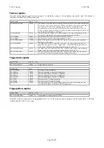
Features register
All of this features Registers may be set by writing a 1 or cleared by writing a 0. Some features may only be used if this features is
installed on the board (see PCI Features above).
register name
reg no.
r/w
SPC_EXTERNALCLOCK
20100
w
The external clock will be used for recording. The external clock will be used as sample clock
for the adcs. The clock must be between 150 kHz and 40 MHz. If the interlace mode should
be used write a 80 MHz to the samplerate register, otherwise write 40 MHz to the
samplerate register. No other values should be used, when the external clock is fed in the
system. In interlace mode, both edges of the clock are used: An external clock of 30 MHz will
result in 60 MHz recording on one channel.
SPC_EXTERNOUT
20110
w
The sampling clock will be put out on BNC-connector 3. The output will generate a 12.5 ns
low pulse on every sample. The maximum output sampling speed is 40 MHz.
SPC_50OHM0
30030
w
Set the channel 0 to 50
:
input resistance (default is 1 M
:
).
SPC_50OHM1
30130
w
Set the channel 1 to 50
:
input resistance(default is 1 M
:
).
SPC_PATTERNENABLE
110000
w
Read out the digital channels if installed. If this register is not set, data will be expanded in
hardware to 16 bit integer.
SPC_TRIGGEROUT
40100
w
The trigger event will be put out on BNC connector 2. The output will generate a positive
edge when the trigger event occurs. Trigger output is not possible if the trigger connector is
used as input. The option is available in boards starting with version 3.3.
SPC_TRIGGER50OHM
40110
w
The trigger input is put to ground with 50 Ohm. This option may only be used if an external
trigger is used. The option is available in boards starting with version 3.3.
SPC_CLOCK50OHM
20120
w
The clock input is put to ground with 50 Ohm. This option may only be used if an external
clock is used. The option is available in boards starting with version 3.3.
Triggermode register
register name
reg no.
r/w
SPC_TRIGGERMODE
40000
w
Triggermode for recording.
triggermodes
value
TM_SOFTWARE
0
Recording will start immediately.
TM_CH0POS
10000
Wait for rising edge on channel 0 at triggerlevel.
TM_CH0NEG
10010
Wait for falling edge on channel 0 at triggerlevel.
TM_CH1POS
10100
Wait for rising edge on channel 1 at triggerlevel.
TM_CH1NEG
10110
Wait for falling edge on channel 1 at triggerlevel.
TM_TTLPOS
20000
Wait for external TTL trigger rising edge.
TM_TTLNEG
20010
Wait for external TTL trigger falling edge.
TM_PATTERN
21000
Wait for digital pattern. The pattern trigger is level sensitive. For this recording may start
immediatly if the digital inputs already hold the trigger pattern.
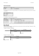
Triggerpattern register
register name
reg no.
r/w
SPC_TRIGGERPATTERN
43000
w
triggerpattern for triggermode TM_PATTERN
The digital inputs are compared to the triggerpattern. Bit 0 to 7 of the value are used to compare with the digital inputs. In 80 MHz
interlace mode only bit 0 to 3 are used.


