7
3. DEVICE AND PRINCIPLE OF OPERATION
3.1. The principle of operation of the metal stress
indicator is based on the measurement of the magnetic field
strength over the surface of the residual magnetized area of the
metal (the field strength of the residual magnetization of the
metal).
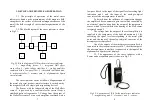
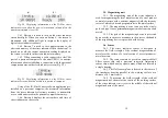
3.2. The block diagram of the stress indicator is shown
in Fig.3.1.
Fig.3.1. Block diagram of IN-01m the metal stress indicator
1 – magnetizing device, 2 – integrated Hall effect
sensor chip, 3 – pulse voltage stabilizer, 4 – scaling amplifier
combined with a low-pass filter, 5 – threshold indication unit,
6 – microcontroller, 7 – memory card, 8 – alphanumeric liquid
crystal display.
The stress indicator works as follows. Magnetization of
the metal of a steel product, metal structure is carried out by
the magnetic field of a single-pole magnetizing device 1.
The Sensor with the integrated chip of the Hall effect
sensor 2 is powered by a constant electric current from a
stabilized pulse voltage source 3. Voltage from the output of
the Hall effect sensor 2 via a scale amplifier combined with a
4
6
7
5
3
2
1
8
8
low-pass filter 4 to the input of the signal level exceeding light
indication unit 5 and the input of the analog-to-digital
converter of the microprocessor controller.
To detach from the influence of temperature changes
the amplifier 4 has an automatic gain control unit controlled by
an electrical signal coming from the output of the temperature
sensor, which is located inside the housing of the Hall sensor
integrated circuit 2.
The voltage from the output of the scale amplifier 4 is
supplied to the comparator of the light indication unit 5 for
exceeding the signal level corresponding to the metal yield
point, and the input of the analog-to-digital converter of the
microprocessor controller 6.
One of the outputs of the microprocessor controller 6 is
connected to the electronic memory card 7, the other output of
the microprocessor controller 6 is connected to the input of the
alphanumeric liquid crystal display 8.
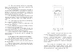
3.3. The appearance of the stress indicator with a
Sensor and a magnetizing unit is shown in Fig.3.2.
Fig.3.2. Appearance of IN-01m the metal stress indicator
1 – magnetizing unit, 2 – electronic unit, 3 – sensor.
1
2
3


