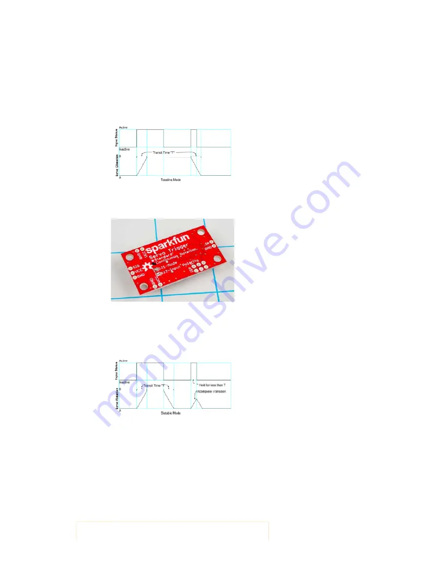
The Servo Trigger has two different servo control modes, selected with
solder jumper 1 (SJ1). They can be used to tailor the response of the board
for different applications.
The default mode implements
toggling
control. The trigger initializes
driving the servo as instructed by trimmer
A
. When the switch closes, it
transitions to the speed indicated by
B
. When the switch closes again, it
returns to
A
. The time taken to get between
A
and
B
is selected using
trimmer
T
, which ranges from nearly instantaneous to 10 seconds,
allowwing the motor to gradually slow, stop, and reverse.
Mode Jumper Cleared - Toggling Control
This behavior can be changed by flowing solder between the pads of the
mode jumper.
Closing SJ1 to select bistable mode.
With the solder jumper closed, the mode changes to
bistable
control – the
servo will drive at speed A while the switch is open, and speed B while the
switch is closed. While the switch input stays in a state, the servo drives at
the corresponding speed – it is
stable
in
two
different states.
Mode Jumper Cleared - Bistable Control
Input Polarity
The Servo Trigger input sensitivity can also be changed, using solder
jumper 2 (SJ2).
The default configuration, with no solder applied, configures the Servo
Trigger for use with a normally-open switch, with the internal pull-up resistor
on the microcontroller enabled. This configuration is also suitable for use
with an active-low logic input.
With SJ2 closed, the internal pull-up is disabled, and the input is set as an
active-high logic input.
Page 7 of 13


