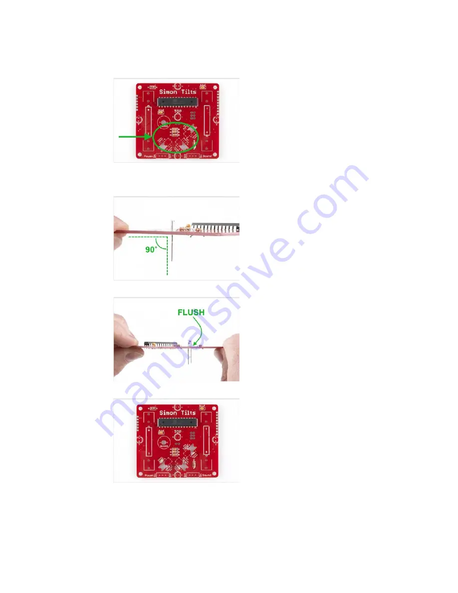
Locate the positions on the board. Notice that there are “Yellow Emittor”
and “Red Detector” labels printed on the PCB. Also note that there are “-”
and “+” marks for each leg. Be careful here to ensure correct placement
and polarity.
When soldering these into place, make sure they are positioned straight up
(vertically). Check that your legs are forming a 90 degree angle with the
PCB like so:
Also ensure that they are flush to the PCB:
When you’re done soldering all 6 into place, your PCB should look like this:
To learn more about how IR emitters and detectors work, check out this
video: SparkFun Infrared Sensor Overview
Buzzer and Switches
Locate the buzzer and slide switches:
Page 9 of 20


