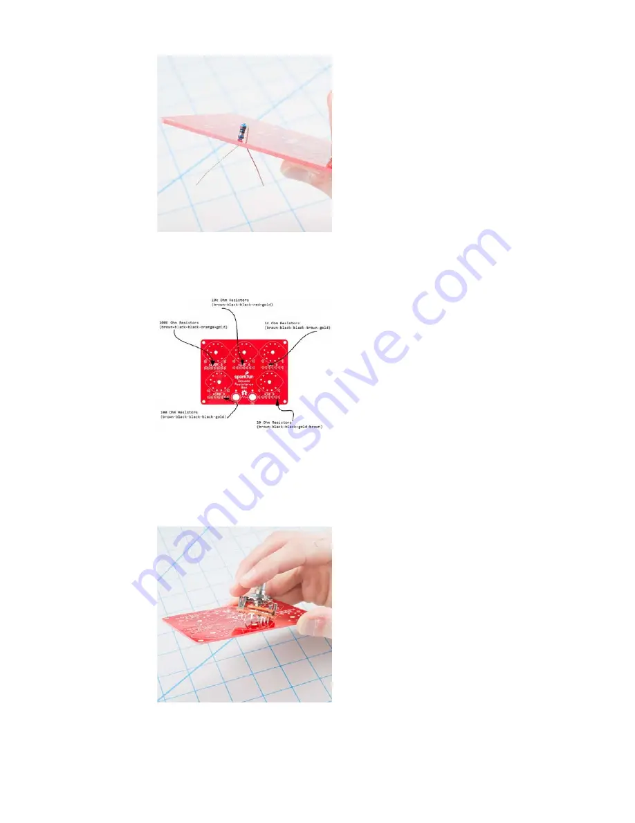
After soldering each resistor, trim the leads close to the solder fillet.
There are nine pieces of each of five different resistance values in the kit.
Each value will be installed adjacent to each rotary switch. Each row is
labeled with the value to be installed there.
If you’re unsure about reading the stripes on the resistors, you can use a
multimeter to verify their value.
Soldering Rotary Switches
After the resistors are in place, install the rotary switches. The rotary
switches fit within the matching outlines on the board. The footprint is
slightly asymmetrical, so they only fit the PCB in one orientation.
The five switches are all the same, and interchangable on the PCB. Insert
them into the footprint, and solder all eleven leads in place. If you’re going
to put the decade box in an enclosure, ensure that the switches sit flat on
the surface of the board before soldering.
Page 6 of 16


