background image


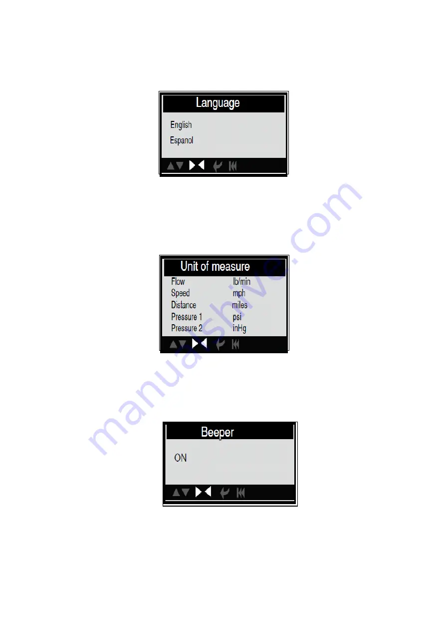
1). Select language:

 Selects desired language. 

Choose [Language] and press [ENTER], the screen will display the interface as shown 

below: 


You can press [UP] [DOWN] key to select any language and press [ENTER] 

The system will convert to the chosen language interface at once. 


2). Unit of measure. 

Choose [Unit of measure] and press [ENTER], the screen will display the interface as 

shown below: 


Press [UP] or [DOWN] to select it and press [LEFT] and [RIGHT] to change, then press 

[ENTER] to confirm.  


3). Beeper:

 ON/OFF the Beeper. 

Choose [Beep] and press [ENTER], the screen will display the interface as shown below: 


Press [ENTER] to select ON/OFF and press [ESC] to confirm. 


Summary of Contents for SP61155

Page 1: ...IONS AND ATTACH RECEIPT TO MANUAL FOR FUTURE REFERENCE NOTE Proof of purchase must be retained by the customer as it will be required in the event of a claim under warranty AFTER SALES SUPPORT AUSTRAL...

Page 2: ...DTCs 4 2 3 Location of the Data Link Connector DLC 4 2 4 OBD II Readiness Monitors 4 2 5 OBD II Monitor Readiness Status 5 2 6 OBD II Definitions 5 3 Using the Scan Tool 6 3 2 Specifications 7 3 5 To...

Page 3: ...can tool dry clean free from oil water or grease Use a mild detergent on a clean cloth to clean the outside of the scan tool when necessary 2 General Information 2 1 On Board Diagnostics OBD II The fi...

Page 4: ...board computer The DLC is usually located 12 inches from the centre of the instrument panel dash under or around the driver s side for most vehicles If Data Link Connector is not located under dashbo...

Page 5: ...monitor is set as Ready or Complete it will remain in this state A number of factors including erasing of diagnostic trouble codes DTCs with a scan tool or a disconnected battery can result in Readin...

Page 6: ...its onboard diagnostics Some form of a drive cycle needs to be performed after DTCs have been erased from the PCM s memory or after the battery has been disconnected Running through a vehicle s compl...

Page 7: ...C 32 to 122 F Storage temperature 20 to 70 C 4 to 158 F RH60 Outline dimension 11 5 8 2CM L W H Weight 200g 7 12 oz 3 3 Accessories Included User Manual Show the user how to operate the tool CD Inclu...

Page 8: ...onvert to the chosen language interface at once 2 Unit of measure Choose Unit of measure and press ENTER the screen will display the interface as shown below Press UP or DOWN to select it and press LE...

Page 9: ...rs and light trucks sold in the world must be OBD II compliant and this includes all America Asian and European vehicles Press ENTER to select ON OFF and press ESC to confirm When this function is ON...

Page 10: ...ter finishing press ENTER button to enter Main Menu as following picture CAUTION Don t connect or disconnect any test equipment with ignition on engine running 4 2 OBDII Diagnose Select OBDII Diagnose...

Page 11: ...figure to select different item by pressing UP or DOWN and press ENTER to confirm 1 3 indicates there are 3 codes totally and now P0143 is the first code to display The screen will also show the cont...

Page 12: ...display the interface as shown on the next page Notes Before performing this function make sure to retrieve and record the trouble codes After clearing you should retrieve trouble codes once more or...

Page 13: ...their designated sections of the vehicle system The I M Readiness Monitor Status function also can be used after repair of a fault has been performed to confirm that the repair has been performed corr...

Page 14: ...ll display the interface as shown below Select View All Items and press ENTER button the screen will display the interface as shown below You can use LEFT RIGHT button to view other data streams Press...

Page 15: ...screen will display the interface as shown on the next page After selected items and press ESC the screen will display the interface as shown below Press ESC to return to Diagnostic Menu Select View...

Page 16: ...in item of live data with a graph 4 2 5 View Freeze Frame When an emission related fault occurs certain vehicle conditions are recorded by the on board computer This information is referred to as free...

Page 17: ...the list generated will vary depending on vehicle In addition not all vehicles support the Oxygen Sensors screen Select O2 Sensor Test in Diagnostic menu and press ENTER and the screen will display a...

Page 18: ...ESC to return to Diagnostic Menu 4 2 8 EVAP System Test The EVAP test function lets you initiate a leak test for the vehicle system The AUTO SCANNER does not perform the leak test but signals to vehic...

Page 19: ...er as shown below Press ESC to return to Diagnostic Menu 4 3 JOBD Diagnose Select JOBD Diagnose in Main Menu and press ENTER the screen will display the following menu Use Up or Down button to select...

Page 20: ...face as shown below Press UP or DOWN button to select View All Items Select Items and press ENTER button to confirm the screen will display the relative data Note during the operation to view differen...

Page 21: ...ESC to return to the Main Menu 4 5 Review History This function is used to review the recorded Data Streams DTC and Freeze Frame Select Review History in the Main Menu and press ENTER and the screen...

Page 22: ...nterface as shown below Press ENTER to confirm and press ESC to return to Main Menu 5 Delete Data stream The operation is similar to the Delete DTC function 6 Delete Freeze Frame The operation is simi...

Page 23: ...Relevant introductions information about Data stream Select About Data stream in the Help Menu and press ENTER and the screen will display the interface as shown below Select the data stream item and...

Page 24: ...or normal wear and tear 1 2 Has been used in a manner other than for which it was originally designed 1 3 Has been tampered with or is otherwise than as supplied by SP Tools 1 4 Where any damage malfu...

Reviews: