background image

Chapt

er

 4   
Re
c

o

rdin

g/

Pla

y

ba
c

k

56

4-2 Playback

4-2 Playback

This section describes playback of video and audio.

Disc playback start position

Although this unit uses optical discs, it is designed to offer 
the most convenient features of tape playback by VTRs. 
One of these is the playback start position, which works in 
the same way as tape, as described below.

After playback stop

The unit stops at the position where the STOP button was 
pressed.
Press the PLAY button to resume playback at the stop 
position.

After recording

The unit stops at the position where recording ended.

To play back a clip, press the PREV button to move to the 
start frame of any clip, or press the PREV button with the 
PLAY button held down to move to any position.

After disc insertion

The unit stops at the position of the disc when it was most 
recently ejected.
Press the PLAY button to resume playback at the most 
recent position.
The playback position is saved to the disc when the disc is 
ejected, which allows playback to start at that position 
whenever it is loaded into any XDCAM player.

Note

This function is not available when the Write Inhibit tab of 
the disc is set to the recording disabled position, and when 
extended menu item 310 “REC INHIBIT” is set to “on.”
The REC INH indicator may light when neither of the 
above are true if the format of recorded sections on the disc 
is not the same as the recording settings of this unit. In this 
case, the playback position can be saved to the disc.

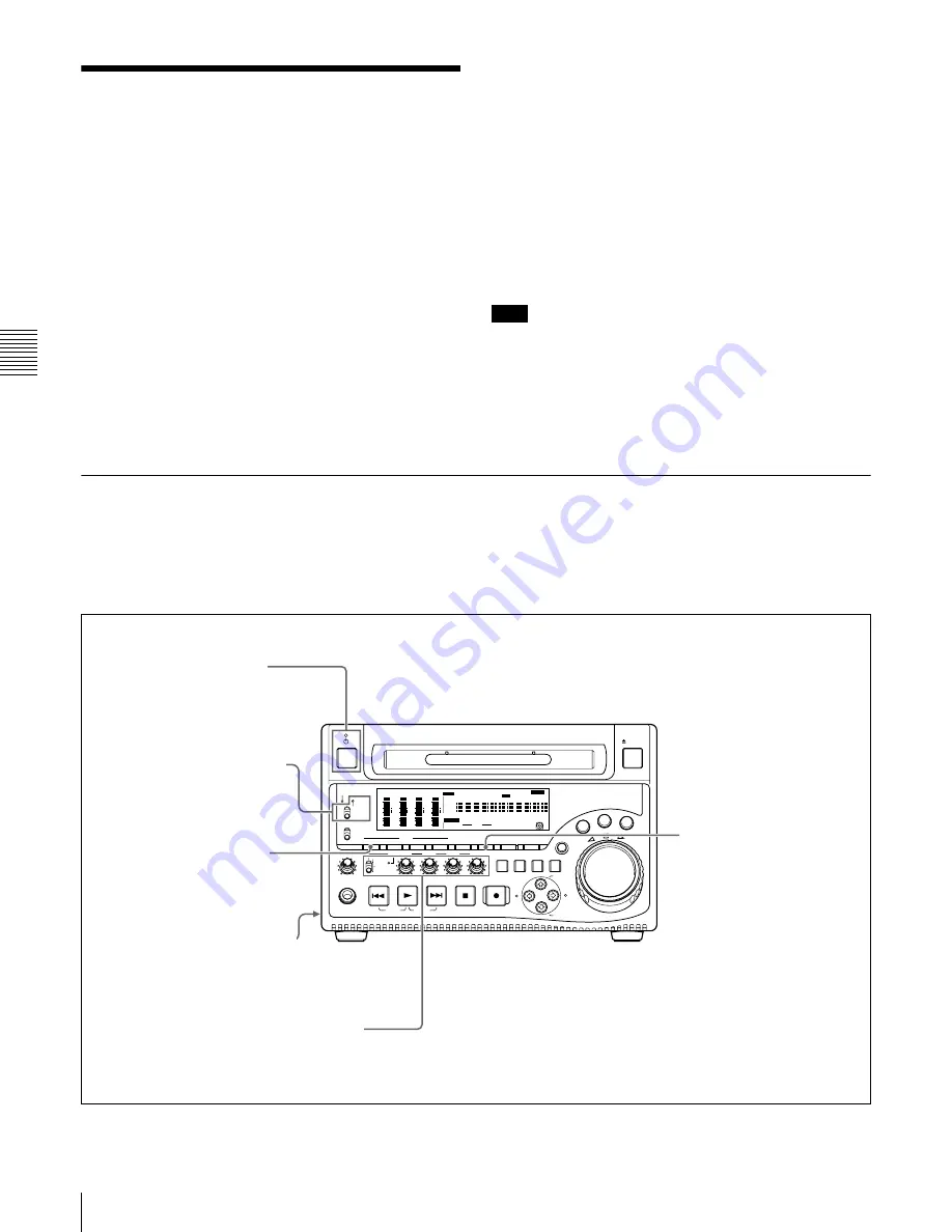
4-2-1 Preparations for Playback

Button/switch settings

Before beginning playback, make any necessary button/
switch settings.

For details of the settings of the buttons/switches, see the 
pages indicated in parenthesis.

REC

VARIABLE

PRESET

PB

L

MIX

R

MONITOR

NETWORK

LOCAL

REMOTE

ACCESS

PHONES

TOP

F REV

F FWD

END

PREV

NEXT

PLAY

AUDIO

MONITOR SEL METER SEL

INPUT CH

INPUT SEL

VIDEO

INPUT SEL

COUNTER

SELECT

SUB

CLIP

THUMB

NAIL

SET RESET

SHIFT

EJECT

HOLD

SYS MENU

MENU

STOP

REC

SH

UTT

LE

JOG

VAR

MARK1

ESSENCE

MARK

CLIP

MENU

S.SEL

MARK2

IN

OUT

ALL/CH-1

CH-2

CH-3

CH-4

OVER

dB

-12

-20

-30

-40

-60

0

CH-   

15

SG DATA
ANA SDI
AE8/EBU

OVER

dB

-12

-20

-30

-40

-60

0

CH-   

26

SG DATA
ANA SDI
AE8/EBU

OVER

dB

-12

-20

-30

-40

-60

0

CH-   

37

SG DATA
ANA SDI
AE8/EBU

OVER

dB

-12

-20

-30

-40

-60

0

CH-   

48

SG DATA
ANA SDI

HOURS

MINUTES

SECONDS

FRAMES

AE8/EBU

VITC

VITC

COUNTER

REC INH

VIUB

EDIT

KEY INH

REMOTE [9P iLINK]

INPUT

i.LINK
SDI

1/2

5/6

3/4

7/8

625

525

IMX[50 40 30]

DVCAM

4 8 CH

18 24 BIT

CMPST
Y-R,B
SG

ALARM

MONITOR

AUDIO

POWER switch 

(page 29):

 I side 

(on)

On/standby switch 

(page 

20):

 Indicator (

"

) lit green.

Audio level adjustment section 

(page 23):


Adjust the audio playback levels

Remote control switch 

(page 

20):

 LOCAL

COUNTER SELECT button 

(page 20):

 Select the data 

(elapsed playback time, time 
code value or user bit data) to 
be displayed in the time data 
display. When displaying the 
time code value, select TC or 
VITC with extended menu 
item 629 “TC SELECT.”

AUDIO MONITOR SEL 

button 

(page 22):

 Select 

the audio channels to 
monitor.

Summary of Contents for XDCAM PDW-1500

Page 1: ...ish 1st Edition Revised 4 The supplied CD ROM includes operation manuals for the PDW 1500 Professional Disc Recorder English Japanese French German Italian Spanish and Chinese versions in PDF format For more details see 1 2 Using the CD ROM Manual on page 17 ...

Page 2: ...ctrical shock do not open the cabinet Refer servicing to qualified personnel only THIS APPARATUS MUST BE EARTHED CAUTION The apparatus shall not be exposed to dripping or splashing No objects filled with liquids such as vases shall be placed on the apparatus The unit is not disconnected from the AC power source mains as long as it is connected to the wall outlet even if the unit itself has been tu...

Page 3: ...NNA BRUKSANVISNING SPECIFICERATS KAN ANVÄNDAREN UTSÄTTAS FÖR OSYNLIG LASERSTRÅLNING SOM ÖVERSKRIDER GRÄNSEN FÖR LASERKLASS 1 For the customers in the USA This equipment has been tested and found to comply with the limits for a Class A digital device pursuant to Part 15 of the FCC Rules These limits are designed to provide reasonable protection against harmful interference when the equipment is ope...

Page 4: ...é Afin d écarter tout risque d électrocution garder le coffret fermé Ne confier l entretien de l appareil qu à un personnel qualifié CET APPAREIL DOIT ÊTRE RELIÉ À LA TERRE ATTENTION Eviter d exposer l appareil à un égouttement ou à des éclaboussures Ne placer aucun objet rempli de liquide comme un vase sur l appareil Cet appareil n est pas déconnecté de la source d alimentation secteur tant qu il...

Page 5: ...ice ou la garantie veuillez consulter les adresses indiquées dans les documents de service ou de garantie séparés AVERTISSEMENT 1 Utilisez un câble d alimentation cordon secteur trifilaire un connecteur d appareil ménager et une fiche avec mise à la terre homologués selon la réglementation de votre pays le cas échéant 2 Utilisez un câble d alimentation cordon secteur trifilaire un connecteur d app...

Page 6: ...ich bitte an die in den separaten Kundendienst oder Garantiedokumenten aufgeführten Anschriften ACHTUNG 1 Verwenden Sie ein geprüftes Netzkabel 3 adriges Stromkabel einen geprüften Geräteanschluss einen geprüften Stecker mit Schutzkontakten entsprechend den Sicherheitsvorschriften die im betreffenden Land gelten 2 Verwenden Sie ein Netzkabel 3 adriges Stromkabel einen Geräteanschluss einen Stecker...

Page 7: ... con questo prodotto aumenta il rischio per la vista CAUTELA L uso di comandi o regolazioni o l esecuzione di procedimenti diversi da quelli specificati in questo manuale possono causare esposizione a radiazioni pericolose AVVERTENZA Un eccessiva pressione sonora da auricolari e cuffie può causare la perdita dell udito Per usare questo prodotto in maniera sicura evitare l ascolto prolungato a live...

Page 8: ...sión Continua Potencia de salida láser 65 mW máx de pico de pulso 35 mW máx de onda continua Esta etiqueta se encuentra en el panel superior de la unidad de mando CAUTION El uso de instrumentos ópticos con este producto aumentará el peligro a los ojos CAUTION La utilización de controles o ajustes o la realización de procedimientos no especificados aquí pueden resultar en la exposición a radiación ...

Page 9: ...las normas de seguridad de cada país si existen 2 Utilice el cable de alimentación 3 conductores eléctricos el conector de dispositivos y el enchufe que cumplen los valores nominales adecuados voltaje amperios Si tiene alguna pregunta acerca del uso del cable de alimentación el conector de dispositivos o el enchufe póngase en contacto con el personal de servicio cualificado ...

Page 10: ...10 ...

Page 11: ...hen Recording Does Not End Normally Salvage Function 47 Chapter 4 Recording Playback 4 1 Recording 49 4 1 1 Preparations for Recording 49 4 1 2 Recording Time Code and User Bit Values 51 4 1 3 Recording Operation 54 4 1 4 Auto Clip List Recording for Automatic Inclusion of Recorded Clips in Clip Lists 55 4 2 Playback 56 4 2 1 Preparations for Playback 56 4 2 2 Playback Operation 57 4 2 3 Thumbnail...

Page 12: ...d FTP Connections 99 Chapter 8 Menus 8 1 Menu System Configuration 101 8 2 Basic Setup Menu 102 8 2 1 Items in the Basic Setup Menu 102 8 2 2 Basic Menu Operations 105 8 3 Extended Menu 109 8 3 1 Items in the Extended Menu 109 8 3 2 Extended Menu Operations 120 8 3 3 Using UMID Data 121 8 4 Maintenance Menu 124 8 4 1 Items in the Maintenance Menu 124 8 4 2 Maintenance Menu Operations 126 8 5 Syste...

Page 13: ...s not set or is cleared in the following situations Reset the line mode The unit is powered off before performing step 4 in the previous procedure The RESET ALL SETUP command in the maintenance menu see page 124 is executed Settings affected by the line mode The following settings are affected when the line mode is changed Alarm message language 525 J Japanese 525 U 625 English The following menu ...

Page 14: ...F MODE Item No item 652 UMID SDI VANC LINE 12 H to 17 H to 19 H 9 H to 17 H to 18 H 660 ESSENCE MARK SDI VANC LINE 12 H to 17 H to 19 H 9 H to 17 H to 18 H 703 BLANK LINE SELECT Setting range ALL LINE LINE 12 to LINE 20 525 U LINE 12 to LINE 21 525 J Setting range ALL LINE LINE 9 322 to LINE 22 335 LINE 23 710 INTERNAL VIDEO SIGNAL GENERATOR BB CB75 CB100 BB CB75 CB100 713 VIDEO SETUP REFERENCE It...

Page 15: ...ing high speed file transfer For high resolution MPEG IMX and DVCAM material the maximum transfer speed is at about 5 times speed for DVCAM signals and about 2 5 times speed for MPEG IMX signals For low resolution proxy AV data a transfer speed of up to 50 times faster than real time is achieved Thumbnail search operation Simply press the THUMBNAIL button and the PDW 1500 instantly displays thumbn...

Page 16: ...e for use with various nonlinear editing systems Analog interfaces Video The unit can input and output a composite analog video signal Audio The unit has two audio channels When in 4 channel mode you can input two channels of audio either as channels 1 and 2 or as channels 3 and 4 The two audio channels can be output also either as channels 1 and 2 or as channels 3 and 4 Digital interfaces SDI Ser...

Page 17: ...tm file on the CD ROM 2 Select and click the operation manual that you want to read This opens the PDF file of the operation manual Memo The files may not be displayed properly depending on the version of Acrobat Reader In such a case install the latest version you can download from the URL mentioned in 1 2 1 Preparations above Note If you have lost or damaged the CD ROM you can purchase a new one...

Page 18: ...Chapter 1 Overview 18 1 3 MPEG 4 Visual Patent Portfolio License ...

Page 19: ... SEL VIDEO INPUT SEL COUNTER SELECT SUB CLIP THUMB NAIL SET RESET SHIFT EJECT HOLD SYS MENU MENU STOP REC SHUTTLE JOG VAR MARK1 ESSENCE MARK CLIP MENU S SEL MARK2 IN OUT ALL CH 1 CH 2 CH 3 CH 4 OVER dB 12 20 30 40 60 0 CH 15 SG DATA ANA SDI AE8 EBU OVER dB 12 20 30 40 60 0 CH 26 SG DATA ANA SDI AE8 EBU OVER dB 12 20 30 40 60 0 CH 37 SG DATA ANA SDI AE8 EBU OVER dB 12 20 30 40 60 0 CH 48 SG DATA AN...

Page 20: ... i LINK input comprising both video and audio signals input to the S400 i LINK connector SDI video signal input to the SDI IN connector Composite video signal input to the VIDEO IN connector Test video signal from the internal signal generator The INPUT display in the status display section changes to reflect the selection as follows i LINKtSDItCMPSTtSG Note Input signals AV C from the S400 i LINK...

Page 21: ...more to turn the button off and return to a whole screen display To display the thumbnails of essence mark frames frames with an essence mark attached hold down the SHIFT button and press this button The essence mark selection menu appears Select the desired type of essence mark and the corresponding essence mark frames appear in thumbnails Press once more turning the button off to return to a who...

Page 22: ...channel display Channel 1 flashing Channel 2 flashing Channel 3 flashing Channel 4 flashing Channels 1 to 4 lit When a channel is flashing you can select the audio input signal using the AUDIO INPUT SEL button When audio is in eight channel mode On channels 5 to 8 you can input only the audio signals embedded in an SDI signal Note After completing the selection of the audio input signals with the ...

Page 23: ...st clip Hold down the SHIFT button and press this button b PLAY playback button To start playback press this button turning it on c NEXT button Press this button turning it on to jump to the next clip and show the first frame This button is also used together with other buttons for the following operations Forward direction high speed search Hold down the PLAY button and press this button A high s...

Page 24: ...The time data display shows the time code When extended menu item 629 TC SELECT is set to tc this shows TC and when vitc is selected it shows VITC UB VIUB user bit type indicator This lights when the COUNTER SELECT button is set to UB The time data display shows the user bits When extended menu item 629 TC SELECT is set to tc this shows UB and when vitc is selected it shows VIUB indicator This lig...

Page 25: ...X40 MPEG IMX 40 format IMX30 MPEG IMX 30 format DVCAM DVCAM format h Disc loaded mark This lights while a disc is loaded in the PDW 1500 It flashes as the disc is inserted and while it is being ejected 6 Shuttle jog variable control block For details of playback operations with these buttons and dials see 4 2 2 Playback Operation on page 57 a SHUTTLE button To play back in shuttle mode using the s...

Page 26: ... dial and start playback in shuttle mode 7 Arrow buttons The four arrow buttons are also used as the MARK1 button MARK2 button IN button and OUT button The correspondence with the buttons is as follows F button MARK1 button f button MARK2 button G button IN button g button OUT button You can use these buttons for thumbnail selection menu setting operations setting IN OUT points and so on a F MARK1...

Page 27: ... device flows into the PDW 1500 This may cause a failure of the PDW 1500 When connecting the PDW 1500 to a device with a 6 pin i LINK connector connect to the 6 pin i LINK connector of the other device first Except in playback mode jog and shuttle modes etc if you are monitoring the audio signal output from this connector on another device the audio signal may sound differently from the audio sign...

Page 28: ... dB Non audio signals are muted See 8 3 2 Extended Menu Operations page 120 for more information about how to make these settings For details of the maintenace menu see 8 4 Maintenance Menu on page 124 2 Digital audio signal inputs outputs a DIGITAL AUDIO AES EBU IN digital audio input 1 2 3 4 connectors BNC type These input AES EBU format digital audio signals The left connector 1 2 corresponds t...

Page 29: ...in the on position and use the on standby switch to switch the PDW 1500 between the operating state and standby state Note When you set the on standby switch on the front panel to the 1 position data is saved before powering off Before turning off the main power switch be sure to check that the on standby switch indicator on the front panel is lit red the PDW 1500 is in the standby state then pres...

Page 30: ...ts 30 2 2 Rear Panel See 8 3 2 Extended Menu Operations page 120 for more information about how to make extended menu settings See 8 4 2 Maintenance Menu Operations page 126 for more information about how to make maintenance menu settings ...

Page 31: ...unit enables you to see the output video on the monitor screen To superimpose text information for example time code and alarm messages use the VIDEO OUT 2 SUPER or SDI OUT 2 SUPER connector You can select the kind of text information to display using basic menu item 005 DISPLAY INFORMATION SELECT For detailed information about basic menu items and how to make menu settings see 8 2 Basic Setup Men...

Page 32: ...ded in the software Using the network connector FTP connection The following shows an example of an FTP File Transfer Protocol connection Note To use PDZ 1 requires the PDW 1500 IP address and other network related settings to be made beforehand For details of the network related settings see To change network settings page 127 1 PDW 1500 1 Network cable not supplied Laptop computer network connec...

Page 33: ...ftware page 78 for more information about installing the PDZ 1 software Some limitations apply to FAM connections For details see 7 2 File Access Mode File Operations page 89 PDW 1500 PDW 1500 PDW 1500 1 1 1 1 1 Network cable not supplied Laptop computer network connector To network connector Connecting three PDW 1500 units to a laptop computer via a LAN Make sure the remote control switch see pag...

Page 34: ...election Use extended menu item 831 DV OUT AUDIO MODE to select either of the following 4ch 12 bit 32 kHz 4 ch 2ch 16 bit 48 kHz 2 ch Factory default setting Audio output channel selection Select the audio output channels with extended menu item 828 SDI DV AUDIO OUTPUT SELECT For information about how to make extended menu item settings see 8 3 2 Extended Menu Operations on page 120 For the method...

Page 35: ...1 RECORDER BVE 700 COMPOSITE VIDEO OUTPUT 3 SUPER AUDIO MONITOR OUT REMOTE 2 2 1 1 1 1 1 3 Cut editing system comprising this unit as a player an MSW M2000 M2000P unit as a recorder and a BVE 700 editing control unit 1 75 Ω coaxial cable not supplied 2 9 pin remote control cable not supplied 3 Cable with RCA phono plugs not supplied Video monitor Video monitor To composite video input connector To...

Page 36: ...or Video monitor To composite video input connector To analog audio input connector To composite video input connector Connections using the REMOTE connector D sub 9 pin Cut editing system comprising this unit as a player and an MSW M2000 M2000P unit as a recorder For cut editing the system uses the editing functions of the recorder MSW M2000 M2000P recorder settings REMOTE 1 9P button Unlit For d...

Page 37: ...the equipment to be connected See page 41 for more information about editing control unit settings VIDEO OUT 2 SUPER VIDEO OUT 3 SUPER AUDIO MONITOR OUT 1 3 2 S400 i LINK 1 Connections using the S400 i LINK connector Cut editing system comprising this unit as a player and a DSR 2000 2000P unit as a recorder For cut editing the system uses the editing functions of the recorder In this system all si...

Page 38: ...75 Ω coaxial cable not supplied 2 9 pin remote control cable not supplied 3 Cable with RCA phono plugs not supplied Video monitor To composite video input connector Reference video signal M2000P recorder Video monitor To composite video input connector To analog audio input connector MSW M2000 M2000P player settings REMOTE 1 9P button Lit For details about the settings of the MSW M2000 M2000P refe...

Page 39: ...te control cable not supplied 3 Cable with RCA phono plugs not supplied Video monitor To composite video input connector Reference video signal M2000P recorder Video monitor To composite video input connector To analog audio input connector MSW M2000 M2000P player settings REMOTE 1 9P button Lit For details about the settings of the MSW M2000 M2000P refer to the operation manual for the unit PDW 1...

Page 40: ...supplied 3 Cable with RCA phono plugs not supplied Video monitor To composite video input connector Reference video signal M2000P recorder Video monitor To composite video input connector To analog audio input connector MSW M2000 M2000P player settings REMOTE 1 9P button Lit For details about the settings of the MSW M2000 M2000P refer to the operation manual for the unit PDW 1500 recorder settings...

Page 41: ...itches as follows Left switch Right switch PVE 500 No settings required Line mode VTR CONSTANT 1 VTR CONSTANT 2 1 2 3 4 5 6 7 8 1 2 3 4 5 6 7 8 525 60 A0 91 00 96 05 05 03 80 0A 07 FE 00 80 5A FF 5A 625 50 A1 91 00 7D 05 05 03 80 0A 07 FE 00 80 4C FF 4B Line mode 1 2 3 4 5 6 7 8 9 10 11 12 13 14 15 525 60 A0 91 00 96 05 05 03 80 0A 07 FE 00 80 5A FF 625 50 A1 91 00 7D 05 05 03 80 0A 07 FE 00 80 4C...

Page 42: ...his unit for the first time you should set the date and time as follows 1 Holding down the SHIFT button press the MENU button The system menu appears on the monitor screen 2 Select DATE TIME PRESET using the F button or f button then press the g button The date and time setting screen appears on the monitor allowing you to set the following items YEAR Calendar year MONTH Month DAY Day TIME Time TI...

Page 43: ... superimposed text using basic menu items 002 003 005 009 011 and 012 For details see 8 2 1 Items in the Basic Setup Menu page 102 Information displayed Note The display shown above corresponds to the factory default settings of the unit You can change the type of information to be displayed in the lower line of the display by changing the setting of basic menu item 005 DISPLAY INFORMATION SELECT ...

Page 44: ...erator time code UBG TC generator user bits data IN IN point time data OUT OUT point time data DUR Duration between IN point and OUT point Display Description B1 The current menu settings are the same as the settings in menu bank 1 B2 The current menu settings are the same as the settings in menu bank 2 B3 The current menu settings are the same as the settings in menu bank 3 B4 The current menu se...

Page 45: ...heck the total optical output time of optical heads For details see 9 1 1 Digital Hours Meter page 133 about this setting Refer to the Maintenance Manual for an approximate guide to when it is time to replace optical heads To prevent playback conditions from deteriorating Pay attention to the following points when handling discs Do not open disc cartridges and touch discs directly with your hands ...

Page 46: ...ion Storage Do not store discs where they may be subjected to direct sunlight or in other places where the temperature or humidity is high Do not leave cartridges where dust may be able to gain ingress Store cartridges in their cases Care of the discs Remove dust and dirt on the outside of a cartridge using a soft dry cloth If condensation forms allow ample time to dry before use 3 5 3 Write Prote...

Page 47: ... removed This operation should always be done by a trained service technician For details refer to the Maintenance Manual 3 5 7 Handling of Discs When Recording Does Not End Normally Salvage Function Recording processing does not end normally if for example the POWER switch on the rear panel is turned off during recording or if the power cord is disconnected during recording Because the file syste...

Page 48: ...sc Nonvolatile memory cannot be used so processing takes longer than for a quick salvage about 30 seconds although it depends on the state of the disc Proceed as follows to perform a full salvage 1 Insert the disc on which recording did not end normally The message Salvage appears 2 Do one of the following To salvage Press the SET button Processing begins and the message Executing appears Notes If...

Page 49: ...ATA ANA SDI AE8 EBU OVER dB 12 20 30 40 60 0 CH 37 SG DATA ANA SDI AE8 EBU OVER dB 12 20 30 40 60 0 CH 48 SG DATA ANA SDI HOURS MINUTES SECONDS FRAMES AE8 EBU VITC VITC COUNTER REC INH VIUB EDIT KEY INH REMOTE 9P iLINK INPUT i LINK SDI 1 2 5 6 3 4 7 8 625 525 IMX 50 40 30 DVCAM 48CH 1824BIT CMPST Y R B SG ALARM MONITOR AUDIO POWER switch page 29 I side on On standby switch page 20 Indicator lit gr...

Page 50: ...ail image When the unit is shipped from the factory it is set up to display the first frame as the thumbnail For example if all clips have the same image in their first frames you can specify a frame a few seconds after the start of the clip so that thumbnails will not all show the same image To specify the frame to use as the thumbnail image Set extended menu item 143 INDEX PICTURE POSITION to a ...

Page 51: ...de recording modes by combining extended menu items settings with video input signal selections To record time code after setting an initial value Set the following extended menu items to the specified values Item 626 TC MODE int preset Item 627 RUN MODE free run or rec run Item 628 DF MODE on df or off ndf See 8 3 2 Extended Menu Operations page 120 for more information about how to make extended...

Page 52: ...ollows sequentially upon the last recorded time code You can record time code so that it is continuous from one clip to the next on the disc Set extended menu item 626 TC MODE to int regen beforehand When this setting is in force the unit reads the time code of the last frame of the last recorded clip on the disc before starting to record and internally generates time code that follows upon the re...

Page 53: ...e INPUT display select i LINK To synchronize to i LINK VITC Connect an i LINK signal to the S400 i LINK connector Press the VIDEO INPUT SEL button and while viewing the INPUT display select i LINK 2 Make the following settings To synchronize to time code input to the TIME CODE IN connector Set extended menu item 626 TC MODE to ext regen Set extended menu item 629 TC SELECT to tc To synchronize to ...

Page 54: ...ay select i LINK 2 Press the MENU button and set extended menu item 626 TC MODE to ext preset For details of menu setting operations see Chapter 8 Menus page 101 4 1 3 Recording Operation To record proceed as follows 1 Insert a disc For details see 3 5 4 Loading and Unloading a Disc on page 46 2 Hold down the REC button and press the PLAY button Recording starts 3 To stop recording press the STOP ...

Page 55: ...to clip list recording is a function for automatically including the clips generated by recording operations in a selected clip list The updated clip list is saved to the disc Proceed as follows 1 Insert a disc 2 Load a clip list from the disc To create a new clip list load a NEW FILE empty clip list To add clips to an existing clip list load that clip list For operations see 5 3 1 Loading a Clip ...

Page 56: ...s the recording settings of this unit In this case the playback position can be saved to the disc 4 2 1 Preparations for Playback Button switch settings Before beginning playback make any necessary button switch settings For details of the settings of the buttons switches see the pages indicated in parenthesis REC VARIABLE PRESET PB L MIX R MONITOR NETWORK LOCAL REMOTE ACCESS PHONES TOP F REV F FW...

Page 57: ...speed of turning the jog dial The playback speed range is 1 times normal speed To carry out playback in jog mode proceed as follows 1 Press the JOG button turning it on 2 Turn the jog dial in the desired direction at the speed corresponding to the desired playback speed Playback in jog mode starts 3 To stop playback in jog mode stop turning the jog dial When extended menu item 101 SELECTION FOR SE...

Page 58: ...te between normal speed playback and variable speed mode playback Set the shuttle dial to the position corresponding to the desired variable playback speed then switch between normal speed playback and variable speed mode playback by pressing the PLAY and VAR buttons alternately For intermittent variable speed mode playback press the STOP and VAR buttons alternately 4 2 3 Thumbnail Search Cuing up...

Page 59: ...AE8 EBU OVER dB 12 20 30 40 60 0 CH 26 SG DATA ANA SDI AE8 EBU OVER dB 12 20 30 40 60 0 CH 37 SG DATA ANA SDI AE8 EBU OVER dB 12 20 30 40 60 0 CH 48 SG DATA ANA SDI HOURS MINUTES SECONDS FRAMES AE8 EBU VITC VITC COUNTER REC INH VIUB EDIT KEY INH REMOTE 9P iLINK INPUT i LINK SDI 1 2 5 6 3 4 7 8 625 525 IMX 50 40 30 DVCAM 48CH 1824BIT CMPST Y R B SG ALARM MONITOR AUDIO SYS MENU MENU 2 3 3 1 COUNTER ...

Page 60: ...Y button 4 2 4 Clip List Playback You can play back clips in the order of clip lists created with the scene selection function see page 65 Playing back in clip list order Proceed as follows 1 If the clip list that you want to play exists on the disc load it into the current clip list About the current clip list see page 67 For the clip list loading operation see 5 3 1 Loading a Clip List From Disc...

Page 61: ...through the last clip on the disc Clip list playback When playback of the last sub clip finishes it resumes from the start of the clip list repeatedly playing from the first through the last sub clip in the clip list If extended menu item 142 REPEAT MODE is set to play repeat playback starts from the first clip automatically whenever you power the unit on with a disc loaded Clip list playback star...

Page 62: ...own press the SUBCLIP button Or press the MENU button The THUMBNAIL MENU appears To escape from the THUMBNAIL MENU to the previous screen Press the RESET button 4 With LOCK UNLOCK CLIP selected press the SET button You return to the thumbnail screen and a lock icon appears on the thumbnail of the selected clip to show that it is locked Locked clips cannot be deleted or renamed Unlock the clip if y...

Page 63: ...pe from the THUMBNAIL MENU to the previous screen Press the RESET button 4 Use the arrow buttons or the jog dial to select DELETE CLIP and then press the SET button Thumbnails of four frames in the target clip appear One of the following messages appears in a confirmation dialog depending on whether the target clip is referenced in a clip list When the target clip is not referenced in a clip list ...

Page 64: ...Chapter 4 Recording Playback 64 4 2 Playback ...

Page 65: ...ips from the material recorded on a disc and perform cut editing You can do this by operating on this unit only Scene selection is a convenient way to perform cut editing in the field and in other offline situations Clip lists edit data created with the scene selection function can be used on XPRI and other full feature nonlinear editing systems ...

Page 66: ... Reordering sub clips see page 70 Trimming sub clips see page 72 Deleting sub clips see page 73 Previewing clip lists see page 73 Save the clip list to disc see page 73 Play back the clip list see page 60 Disc PDW 510 530 PDW 1500 Clip 1 Clip 2 Clip 3 Sub clip 1 Sub clip 2 Sub clip 3 Clip 1 Clip 2 Clip 3 Clip list 1 Disc Sub clip 1 Sub clip 2 Sub clip 3 PDW 1500 Recorded material Clip list 1 Selec...

Page 67: ...re virtual data specifying ranges in the original clips Clip data in the original clips is not overwritten Clip list editing current clip list Clip lists cannot be edited on disc To edit clip lists you need to load them one at a time into the unit memory The clip list which is currently loaded into the unit memory is called the current clip list The current clip list is always the target of sub cl...

Page 68: ...nd thumbnail display C0001 Clip 1 C0002 Clip 2 C0003 Clip 3 E0001 Clip list 1 E0002 Clip list 2 E0003 Clip list 3 E0099 Clip list 99 M LOAD Disc REC VARIABLE PRESET PB L MIX R MONITOR NETWORK LOCAL REMOTE ACCESS PHONES TOP F REV F FWD END PREV NEXT PLAY AUDIO MONITOR SEL METER SEL INPUT CH INPUT SEL VIDEO INPUT SEL COUNTER SELECT SUB CLIP THUMB NAIL SET RESET SHIFT EJECT HOLD STOP REC SHUTTLE JOG ...

Page 69: ...the same clip any number of times The scene selection window displays thumbnails of the sub clips that have been added to the current clip list The cursor in the window indicates the position where the next sub clip will be added To move the cursor in the scene selection window After carrying out step 3 to display the scene selection window press the G or g button 6 When you have finished selectin...

Page 70: ...rent Clip List to Disc page 73 5 2 2 Reordering Sub Clips 1 Press the SUBCLIP button turning it on 2 Press the THUMBNAIL button turning it on Thumbnails of the sub clips in the current clip list appear If the clip list you want to edit is not the current clip list Clip 1 Sub clip 1 Clips recorded on the disc Clip 2 Clip 3 Sub clip 2 Sub clip 3 In point Out point REC VARIABLE PRESET PB L MIX R MONI...

Page 71: ...n to the thumbnail screen without moving the sub clip Do one of the following Press the F or f button to select EXIT and then press the SET button Press the RESET button 5 Use the F or f button to select MOVE and then press the SET button The sub clip movement screen appears The clip selected in step 3 appears surrounded by a frame To return to the previous screen Press the RESET button 6 Use the ...

Page 72: ...utton Note You can escape from the sub clip trim screen to full screen display without executing a trim if you press the THUMBNAIL button 5 Once you have set the new In point or Out point hold down the SHIFT button and press the SET button The trim is executed and you return to the sub clip thumbnail display To cancel the trim Reset the In or Out point to the value it had before you entered the su...

Page 73: ...aved to disc unless you carry out this procedure After editing clip list data you should always save it to disc Notes The current clip list is not saved to disc if the Write Inhibit tab of the disc is set to the recording disabled position Unless you carry out this procedure the unit does not enter the standby state even if you set the on standby switch to the 1 position Follow the message that ap...

Page 74: ... 1 software For details refer to the PDZ 1 online help REC VARIABLE PRESET PB L MIX R MONITOR NETWORK LOCAL REMOTE ACCESS PHONES TOP F REV F FWD END PREV NEXT PLAY AUDIO MONITOR SEL METER SEL INPUT CH INPUT SEL VIDEO INPUT SEL COUNTER SELECT SUB CLIP THUMB NAIL SET RESET SHIFT EJECT HOLD STOP REC SHUTTLE JOG VAR MARK1 ESSENCE MARK CLIP MENU S SEL MARK2 IN OUT ALL CH 1 CH 2 CH 3 CH 4 OVER dB 12 20 ...

Page 75: ...on REC VARIABLE PRESET PB L MIX R MONITOR NETWORK LOCAL REMOTE ACCESS PHONES TOP F REV F FWD END PREV NEXT PLAY AUDIO MONITOR SEL METER SEL INPUT CH INPUT SEL VIDEO INPUT SEL COUNTER SELECT SUB CLIP THUMB NAIL SET RESET SHIFT EJECT HOLD STOP REC SHUTTLE JOG VAR MARK1 ESSENCE MARK CLIP MENU S SEL MARK2 IN OUT ALL CH 1 CH 2 CH 3 CH 4 OVER dB 12 20 30 40 60 0 CH 15 SG DATA ANA SDI AE8 EBU OVER dB 12 ...

Page 76: ... display of dates of creation titles and clip list names With the SHIFT button held down press the SET button With each press the display changes as follows Dates of creation titles clip list names dates of creation 3 Use the F or f button or the jog dial to select the desired clip list and then press the g button A confirmation message like the one shown below appears 4 Press the SET button The s...

Page 77: ...st is set When the clip list is played back time code will start counting from that value To check the time code after setting it Press the SUBCLIP button turning it on The initial time code of the current clip list appears in the TCR field 6 Save the current clip list to disc See 5 2 6 Saving the Current Clip List to Disc page 73 5 3 5 Sorting Clip Lists Proceed as follows to sort the existing cl...

Page 78: ...e PDZ 1 Computer When using the live logging function PC with Intel Pentium 4 CPU at least 2 GHz installed memory at least 512 MB When not using the live logging function PC with Intel Pentium III CPU at least 1 GHz installed memory at least 512 MB Operating system Microsoft Windows 2000 Service Pack 4 or higher or Microsoft Windows XP Professional Service Pack 1 or higher Web browser Internet Exp...

Page 79: ...els 1 According to the setting of maintenance menu item AUDIO CONFIG DATA LENGTH Available audio signals Audio signals input to the following connectors can be inserted into the audio tracks of clips ANALOG IN 1 3 and 2 4 connectors DIGITAL AUDIO AES EBU IN 1 2 and 3 4 connectors SDI IN connector Notes Audio signals input to the S400 i LINK connector cannot be inserted Audio insert editing cannot ...

Page 80: ...bout how to make this setting Audio Non audio data To perform insert editing of non audio data set maintenance menu AUDIO CONFIG NON AUDIO INPUT see page 124 to data See 8 4 2 Maintenance Menu Operations page 126 for more information about how to make this setting Note When you insert non audio into a clip the channels containing the non audio are treated as non audio across their entire length Us...

Page 81: ...Set MIXING in extended menu item 819 AUDIO INPUT SOURCE ARRANGE to on and set CH1 to on See 8 3 2 Extended Menu Operations page 120 for more information about how to make these settings 4 Adjust the input signal level see page 23 Note The level of audio signals recorded on the disc cannot be adjusted 5 Execute a clip audio insert edit ...

Page 82: ...Chapter 6 Insert Editing 82 6 1 Clip Audio Insert Editing ...

Page 83: ... Connect the network connectors on this unit and the remote computer using a network cable see page 91 7 1 1 Directory Structure The following figure shows the directory structure of discs visible to a remote computer Note This structure is not the same as the actual structure recorded on the disc a Root directory b Only when sub item NAMING FORM of basic menu item 036 is set to free root a INDEX ...

Page 84: ...s set to enable recording and when extended menu item 310 REC INHIBIT is set to off With firmware version 1 4x and lower only the most recently recorded clip may be deleted With firmware version 1 5 and higher any clip may be selected and deleted e Only files which can be overwritten by XDCAM f With firmware version 1 5 and higher when the C part of a C MXF file name is changed a C M01 XML with th...

Page 85: ...E E01 SMI file name is changed an E M01 XML file with the same name in the E part is generated automatically g When an E E01 SMI file is created an E M01 XML file with the same name in the E part is created automatically h When an E E01 SMI file is deleted the E M01 XML file with the same name in the E part is also deleted automatically Note Directories cannot be created in the Edit directory Sub ...

Page 86: ... no limits to characters which can be used by FTP connections 7 1 3 Assigning User Defined Clip Titles By default clips on each disc are assigned names in the range C0001 MXF to C4999 MXF For this reason two discs can contain clips with the same names The automatic title generation function 1 allows you to assign titles to all of the clips on several discs which facilitates clip management For exa...

Page 87: ...g the serial number The PREFIX setting is saved in memory banks but the NUMERIC setting is not saved see page 107 7 1 4 Assigning User Defined Clip and Clip List Names The following standard format names are assigned automatically to clips and clip lists that are created or recorded by XDCAM devices Clips C0001 MXF to C4999 MXF Clip lists E0001E01 SMI to E0099E01 SMI This unit can handle clips and...

Page 88: ... the SET button It is now possible to write transfer and rename clips and clip lists with user defined names over file access mode FAM connections see page 89 and FTP connections see page 91 To check clip names Press the THUMBNAIL button to display the thumbnail screen and select the clip whose name you want to check The name of the selected clip appears at the upper left of the screen See Cuing u...

Page 89: ...ting To install the FAM driver Insert the supplied CD ROM PDZ 1 Proxy Browsing Software in the CD ROM drive of the computer and execute the Setup exe file then follow the installation instructions For details refer to the ReadMe file contained on the CD ROM disc Note Use Version 1 4 or higher of the FAM driver The FAM driver on the supplied CD ROM is Version 1 4 or higher If a FAM driver is alread...

Page 90: ...connection the data transferred thus far is discarded All file operations are not possible for some types of files For details see 7 1 2 File Operation Restrictions page 84 To eject discs from a remote computer Right click the icon representing this unit in Explorer and select Eject from the menu which appears 7 2 3 Exiting File Operations Note Do not disconnect the cable before performing steps 1...

Page 91: ...the IP address and other network setting items for this unit For details see To change network settings page 127 If network settings have already been made Check the IP address of this unit For details see To check the assigned IP address page 127 3 Set the remote control switch to NETWORK see page 20 7 3 1 Making FTP Connections FTP connections between this unit and a remote computer can be made ...

Page 92: ...or more information about the FTP command If the connection succeeds you are prompted to enter a user name 4 Enter the user name admin and press the Enter key When the user name is verified you are prompted to enter a password 5 Enter the password and press the Enter key The password is set to pdw 1500 when the unit is shipped from the factory The login is complete when the password is verified Se...

Page 93: ... connection If a file is being transferred terminates after completion of the transfer QUIT CRLF PORT Specifies the IP address and port to which this unit should connect for the next file transfer for data transfer from this unit PORT SP h1 h2 h3 h4 p1 p2 CRLF h1 most significant byte to h4 least significant byte IP address p1 most significant byte p2 least significant byte Port address Input exam...

Page 94: ... about the specified file No specification A list of the files in the current directory The wildcard characters any string and any character may be used in path name Input example 1 LIST a Clip Input example 2 LIST Clip MXF NLST Sends a list of file names from this unit to the remote computer with no other information NLST SP options or path name CRLF The following options may be specified when no...

Page 95: ... as file header metadata may be missing Depending on the transfer destination directory and the file type transfer may not be possible For details see 7 1 2 File Operation Restrictions page 84 STOR SP path name CRLF Input example STOR Edit E0001E01 SMI RNFR RNTO Rename a file Specify the file to be renamed with the RNFR command and specify the new name with the RNTO command Always follow a RNFR co...

Page 96: ... command name is specified with command name Command name specified Explanation of the specified command No specification Command list Input example HELP RETR NOOP Does nothing except return a response Used to check whether this unit is running NOOP CRLF PWD Displays the current directory if the directory is the root directory PWD CRLF CWD Changes the current directory moves from the current direc...

Page 97: ...egment in the body of the MXF file composed of video and audio data for transfer of the required segment only Note A segment greater than the file size cannot be specified SITE REPFL SP path name SP start frame SP transfer size CRLF path name specifies the path name of the file to transfer Enclose the path name in double quotation marks start frame specifies an offset from the start of the file Da...

Page 98: ...is specified in path name 444 Lock 666 Unlock When a directory in the General directory is specified in path name 555 Forbid writing to the directory 777 Allow writing to the directory When a file in the General directory is specified in path name 444 Forbid writing to and execution of the file 555 Forbid writing to the file but allow execution 666 Allow writing to the file but forbid execution 77...

Page 99: ... TC SELECT to tc Then proceed as follows Note Continuous time code cannot be recorded if extended menu item 629 TC SELECT is set to vitc See 8 3 2 Extended Menu Operations page 120 for more information about how to make extended menu settings FAM connection Write clip files to the unit from the computer or other device that is connected to this unit FTP connection Use the STOR command to transfer ...

Page 100: ...Chapter 7 File Operations 100 7 4 Recording Continuous Time Code With FAM and FTP Connections ...

Page 101: ...onfiguration of the basic setup menu The basic setup menu comprises the following groups of items Configuration of the extended setup menu The extended setup menu comprises the following groups of items Item group Function Refer to Items H01 to H17 Display of the total number of hours the unit has been powered on and other information collected by the digital hours meter page 133 Items 001 to 099 ...

Page 102: ...RACTER V POSITION Adjust the vertical screen position as a hexadecimal value of the text information output from the VIDEO OUT 2 SUPER connector and SDI OUT 2 SUPER connector for superimposed display on the monitor 00 2E 38 525 U 525 J line modes 00 37 43 625 line mode The hexadecimal value 00 is for the top of the screen Increasing the value lowers the position of the characters Set this item by ...

Page 103: ...e selected line mode 016 ALARM DISPLAY Select whether or not to display alarm messages off Do not display alarm messages However certain important alarms are displayed limit on limited Display only a minimum number of alarm messages on Display all alarm messages For details about alarm message display conditions see 9 3 1 Alarm List page 135 017 SUB STATUS DISPLAY SELECT Determine the kind of sub ...

Page 104: ...acters are alphanumeric characters symbols _ and the space character TITLE 3 NUMERIC Set the initial value of the numeric part of the title 00001 to 99999 five digit number 00001 036 FILE NAMING b Specify whether to allow use of clip and clip list files with user defined names See 7 1 4 Assigning User Defined Clip and Clip List Names page 87 for details about how to make the settings Sub item 1 NA...

Page 105: ...menu to the factory default settings Set to bank 4 to set the current menu to the settings saved in menu bank 4 off on on default Return the current menu to the factory default settings bank 4 Set the current menu to the settings saved in menu bank 4 Item number Item name Settings REC VARIABLE PRESET PB L MIX R MONITOR NETWORK LOCAL REMOTE ACCESS PHONES TOP F REV F FWD END PREV NEXT PLAY AUDIO MON...

Page 106: ...eir factory default values proceed as follows REC VARIABLE PRESET PB L MIX R MONITOR NETWORK LOCAL REMOTE ACCESS PHONES TOP F REV F FWD END PREV NEXT PLAY AUDIO MONITOR SEL METER SEL INPUT CH INPUT SEL VIDEO INPUT SEL COUNTER SELECT SUB CLIP THUMB NAIL SET RESET SHIFT EJECT HOLD STOP REC SHUTTLE JOG VAR MARK1 ESSENCE MARK CLIP MENU S SEL MARK2 IN OUT ALL CH 1 CH 2 CH 3 CH 4 OVER dB 12 20 30 40 60 ...

Page 107: ...ng the MENU button If you press the MENU button first then the COUNTER SELECT button you can jump directly to menu item B01 or H01 The recalled menu item toggles between B01 and H01 every time you press the COUNTER SELECT button Saving the current active menu settings Set one of basic menu items B11 SAVE SETUP BANK 1 to B13 SAVE SETUP BANK 3 to on depending on which of the menu banks you wish to s...

Page 108: ...in the menu bank When you power the unit off and then on again it will use the line mode and settings of the selected bank To cancel the recall press the MENU button Current active menu settings Menu bank 1 Menu bank 2 Menu bank 3 Recall Save Recall Save Recall Save Menu bank 4 Recall Save RECALL SETUP BANK 1 System will be changed Are you sure you want to execute EXECUTE SET KEY ABORT MENU KEY IT...

Page 109: ...rding inhibit indicator on page 24 off Light the REC INH indicator on Flash the REC INH indicator 108 AUTO EE SELECT When a disc is inserted select the operation modes in which input video and audio signals are automatically handled in E E mode S F R stop f fwd f rev In stop fast forward fast reverse modes stop In stop mode off Do not put the unit into E E mode automatically 109 FORCED EE WHEN DIS...

Page 110: ...e when recording 0sec to 10sec Can be set in the range from 0 seconds first frame of the clip to10 seconds in units of 1 second Menu items in the 100s relating to the control panels Item number Item name Settings Menu items in the 200s relating to the remote control interface Item number Item name Settings 214 REMOTE INTERFACE When the remote control switch is set to REMOTE select the device from ...

Page 111: ...analog ch2 Follow the edit preset of analog channel 2 ch1 2 analog ch1 ch2 Follow the edit preset of analog channel 1 or 2 The default settings for each item are as follows 311 ch 1 analog ch1 312 ch 2 analog ch2 313 nodef no definition 314 nodef no definition 312 ANALOG AUDIO EDIT PRESET REPLACE FOR CH2 313 ANALOG AUDIO EDIT PRESET REPLACE FOR CH3 314 ANALOG AUDIO EDIT PRESET REPLACE FOR CH4 317 ...

Page 112: ... signal generators page 112 The input digital audio signals and video signals must be synchronized with the reference signal input to the REF VIDEO IN connector 344 ASSEMBLE AUTO EDIT POSTROLL RECORDING Set whether or not to record 2 seconds of postroll when an additional clip is recorded by sending the AUTO EDIT command 9 pin protocol 20 42 from a nonlinear editing system connected to the REMOTE ...

Page 113: ...number Item name Settings 501 STILL TIMER To protect the disc against shock and vibrations and to lengthen the life of the laser diodes the unit automatically enters standby off mode whenever a specified time elapses in a disc stop mode stop mode or the still picture mode of search mode This allows you to set the time after which the unit exits a disc stop mode and enters standby off mode 0 5 s 0 ...

Page 114: ...e time code generated by the time code generator 000 000 not specified Character set not specified 001 001 iso character 8 bit characters compliant with ISO 646 and ISO 2022 010 010 unassigned 1 Undefined 011 011 unassigned 2 Undefined 100 100 unassigned 3 Undefined 101 101 page line SMPTE 262M page line multiplex system 110 110 unassigned 4 Undefined 111 111 unassigned 5 Undefined 611 TC OUTPUT P...

Page 115: ... off ndf Non drop frame mode 629 TC SELECT Select the type of time data to show in the time data display and the type of external time code when item 626 is set to ext regen vitc Display time code as VITC or select VITC as the external time code tc Display time code as TC or select TC as the external time code See 4 1 2 Recording Time Code and User Bit Values page 51 for more information about sel...

Page 116: ...nking 10 LINE 20 Specify blanking for line 20 blnk blank Carry out blanking half Carry out half blanking thru throu Switch off blanking 2 10 LINE 12 LINE 20 In 525 J line mode Specify blanking for lines 12 to 20 blnk blank Carry out blanking thru throu Switch off blanking 11 LINE 21 Specify blanking for line 21 blnk blank Carry out blanking half Carry out half blanking thru throu Switch off blanki...

Page 117: ... 0 715 VIDEO GAIN CONTROL Adjust the video output level 512 to 0 to 511 716 CHROMA GAIN CONTROL Adjust the chroma output level 512 to 0 to 511 717 CHROMA PHASE CONTROL Adjust the chroma phase 128 to 0 to 127 718 SETUP LEVEL 525 U 525 J line modes BLACK LEVEL 625 line mode Adjust the setup level black level 512 to 0 to 511 719 SYSTEM PHASE SYNC Adjust the output signal sync phase 128 to 0 to 127 72...

Page 118: ...d wide picture information to the output video signals Notes To add wide picture information to the output signal it is necessary in addition to setting this item to thru to operate extended menu item 703 to set line 20 in 525 line mode to thru or set line 23 in 625 line mode to thru In 525 line mode wide picture information may not be output if VITC signal insertion position is set to line 20 in ...

Page 119: ...aintain current state 2 CH3 CH4 3 CH5 CH6 4 CH7 CH8 824 ANALOG LINE OUTPUT SELECT Select the analog audio signals tracks 1 to 8 to be assigned to audio output channels 1 and 2 tr1 2 Tracks 1 and 2 assigned to audio output channels 1 and 2 tr3 4 Tracks 3 and 4 assigned to audio output channels 1 and 2 tr5 6 Tracks 5 and 6 assigned to audio output channels 1 and 2 tr7 8 Tracks 7 and 8 assigned to au...

Page 120: ...n cause short circuits and lead to failure 828 SDI DV AUDIO OUTPUT SELECT s Select the audio signals to assign to SDI and i LINK AV C audio output channels Sub item 1 CH1 CH2 tr1 2 Tracks 1 and 2 assigned to audio output channels 1 and 2 tr3 4 Tracks 3 and 4 assigned to audio output channels 1 and 2 tr5 6 Tracks 5 and 6 assigned to audio output channels 1 and 2 tr7 8 Tracks 7 and 8 assigned to aud...

Page 121: ... with audio visual data As one of application of metadata the UMID Unique Material Identifier is internationally standardized What is a UMID The UMID Unique Material Identifier is a unique identifier for audio visual material defined by the SMPTE330M 2003 standard The UMID may be used either as the 32 byte Basic UMID or as the Extended UMID which includes an additional 32 bytes of Source Pack to m...

Page 122: ...e MJD Modified Julian Date which enables easy calculation of date difference among source materials Setting UMID ownership information Proceed as follows 1 Set extended menu item 029 STORED OWNERSHIP to on See 8 2 2 Basic Menu Operations page 105 for more information about how to make this setting 2 Set the following item To change the currently selected item Hold down the STOP button and turn the...

Page 123: ... a space ORGANIZATION organization code Enter an abbreviated 4 byte alphanumeric string for the organization code Notes Organization codes must be acquired by applying to the SMPTE registration office When no organization code has been acquired it is forbidden to enter an arbitrary string As a rule the code 00 must be entered Freelance operators who do not belong to an origination should enter The...

Page 124: ...setup menu item 031 this selects the audio quantization bit count and number of recording channels 16 bits 8 channels 24 4 24bit 4ch 24 bits 4 channels Note When item 031 is set to DVCAM the setting is automatically fixed at 16 bits 4 channels NON AUDIO INPUT Select whether to handle digital audio signals as non audio signals during recording Audio audio Handle as audio signals data Handle as non ...

Page 125: ...nk 3 settings in menu bank 4 Reset RESET BANK4 Reset menu bank 4 SAVE MENU DATA Select whether to temporarily back up save setup menu settings before operations such as software upgrades SET button Back up save the settings MENU button Return to next highest menu level without backing up LOAD MENU DATA Select whether to restore load setting that were backed up saved with the SAVE MENU DATA item SE...

Page 126: ...ry out the same operation as in the previous item The currently selected menu item is shown in reverse video on the monitor To change the setting of a menu item To change the setting of the currently displayed menu item carry out the following operations For details of changing settings of network related items see the next item To change network settings OTHERS Item Setting SDI2 SUPER Select whet...

Page 127: ...2 CH 3 CH 4 OVER dB 12 20 30 40 60 0 CH 15 SG DATA ANA SDI AE8 EBU OVER dB 12 20 30 40 60 0 CH 26 SG DATA ANA SDI AE8 EBU OVER dB 12 20 30 40 60 0 CH 37 SG DATA ANA SDI AE8 EBU OVER dB 12 20 30 40 60 0 CH 48 SG DATA ANA SDI HOURS MINUTES SECONDS FRAMES AE8 EBU VITC VITC COUNTER REC INH VIUB EDIT KEY INH REMOTE 9P iLINK INPUT i LINK SDI 1 2 5 6 3 4 7 8 625 525 IMX 50 40 30 DVCAM 48CH 1824BIT CMPST ...

Page 128: ...ET button press the MENU button This returns to the NETWORK CONFIG menu without saving the new setting 5 Repeat steps 1 to 4 as required to set the subnet mask and default gateway 6 In the NETWORK CONFIG menu press the SET button 7 When the NOW SAVING message vanishes power the unit off and then on again with the on standby switch Setting the communications speed Set the communications speed LINK ...

Page 129: ...ftware can write TITLE1 and TITLE2 only TITLE1 is displayed here Sub item 1 DISC Display disc status 2 CLIP Display clip status DELETE Delete clips on the disc Sub item 1 LAST CLIP Delete the last clip 2 ALL CLIP Delete all the clips Locked files and files in the General directory cannot be deleted FORMAT Select the disc format and carry out formatting Sub item 1 QUICK FORMAT Quick format Deletes ...

Page 130: ...e previous section To display disc status and clip status 2 Press the F button or f button to select DELETE then press the g button The DELETE menu item appears 3 Delete the last clip or all clips To delete the last clip Press the F button or f button to select LAST CLIP then press the g button The name of the clip to be deleted appears To cancel the deletion and return to the previous page press ...

Page 131: ...ious page press the RESET button To cancel the deletion and exit the menu system press the MENU button 4 Press the SET button The last clip is deleted or all clips are deleted You can use the THUMBNAIL MENU to delete the selected clip or all clips For details see page 63 To format discs See 3 5 5 Formatting a Disc page 47 To set the date and time See 3 3 Setting the Date and Time page 42 ...

Page 132: ...Chapter 8 Menus 132 8 5 System Menu ...

Page 133: ...cted by the ambient temperature H13 SEEK RUNNING 0 mode resettable Of the two optical heads this shows the cumulative seek operation time for one optical head in units of hours The count is resettable This can be used as a guide in determining when to replace the seek motor H14 SPINDLE RUNNING mode resettable This shows the cumulative spindle rotation time in units of hours The count is resettable...

Page 134: ...PLAY AUDIO MONITOR SEL METER SEL INPUT CH INPUT SEL VIDEO INPUT SEL COUNTER SELECT SUB CLIP THUMB NAIL SET RESET SHIFT EJECT HOLD STOP REC SHUTTLE JOG VAR MARK1 ESSENCE MARK CLIP MENU S SEL MARK2 IN OUT ALL CH 1 CH 2 CH 3 CH 4 OVER dB 12 20 30 40 60 0 CH 15 SG DATA ANA SDI AE8 EBU OVER dB 12 20 30 40 60 0 CH 26 SG DATA ANA SDI AE8 EBU OVER dB 12 20 30 40 60 0 CH 37 SG DATA ANA SDI AE8 EBU OVER dB ...

Page 135: ...llowing tables list the alarms displayed by this unit categorized according to the state of the unit when the alarms occur The setting of basic menu item 016 ALARM DISPLAY determines whether or not some of these alarms appear The Display condition column in the tables shows whether the alarm is displayed according to or regardless of the setting of menu item 016 See 8 2 2 Basic Menu Operations pag...

Page 136: ...ting No FS on limit off The file system cannot be detected Eject the disc ILL Disc on limit off An unsupported disc was inserted Salvage NG on limit off Recovery of disc contents salvage failed See 3 5 7 Handling of Discs When Recording Does Not End Normally Salvage Function page 47 525 60 Clip on limit A disc recorded in NTSC format was inserted when this unit is in 625 line mode PAL system Use a...

Page 137: ...state of a disc by checking playback condition marks see page 44 Message in time data display Display condition a Description Action KEY INHI on An operation button inhibited by extended menu item 118 KEY INHIBIT was pressed while the KEY INH indicator was lit Set the corresponding sub item of extended menu item 118 to off See 8 3 2 Extended Menu Operations page 120 about how to make this setting ...

Page 138: ...d at the end of the disc or an attempt was made to perform a high speed forward search MAX Files on limit off The number of files on the disc had reached the upper limit 5000 or there was not enough capacity in the General directory when an attempt was made to record display an E E picture record an essence mark or add a quick scene selection sub clip Insert a different disc with enough free capac...

Page 139: ...rrent clip list SB CLP mode on limit The SHIFT button and the THUMBNAIL button were pressed together with the SUBCLIP button lit Press the SUBCLIP button turning it off and try the operation again SUB CLIP NG on limit The SHIFT and SET buttons were pressed together when IN and OUT points were not set correctly the OUT point was set before the IN point etc Set the IN and OUT points correctly and tr...

Page 140: ...rch or other command was received with no disc loaded Try the operation again after loading a disc REC INHI on A recording E E display or edit preset command was received for a write protected disc Try the operation again after setting the Write Inhibit tab to the recording enabled position REC INHI on A recording E E display or edit preset command was received with extended menu item 310 REC INHI...

Page 141: ...ence mark or add a quick scene selection sub clip when there was no free Non Real Time space Insert a different disc with enough free capacity No Clip on limit A playback or search command was received for a disc containing no recorded clips These operations are not possible Disc Top on A PREV or reverse high speed search command was received with the disc stopped at the top Disc End on A NEXT or ...

Page 142: ... limit An editing operation was attempted on a recorded disc when one of the following audio settings differed from the settings of this unit Number of quantizing bits and recording channels Handling of digital audio signals audio or non audio To edit this disc change the following settings Maintenance menu item AUDIO CONFIG DATA LENGTH Maintenance menu item AUDIO CONFIG NON AUDIO INPUT See 8 4 2 ...

Page 143: ...r than a standard reference video signal was input to the REF VIDEO IN connector Input a standard reference video signal to the REF VIDEO IN connector No INPUT on An attempt to record was made with no input video signal Input a video signal and select it VIN NON STD on Recording is being done with a signal other than a standard video signal input to the VIDEO IN connector Input a standard video si...

Page 144: ...Chapter 9 Maintenance and Troubleshooting 144 9 3 Alarms ...

Page 145: ... Storage temperature 20ºC to 60ºC 4ºF to 140ºF Operating relative humidity 25 to 90 Mass 7 4 kg 16 lb 5 oz External dimensions w h d excluding projections 210 130 415mm 83 8 51 8 163 8 inches System Recording Playback format Video MPEG IMX 50 40 30 Mbps DVCAM 25 Mbps Proxy video MPEG 4 1 Audio MPEG IMX 16 bits 48 kHz 8 channels or 24 bits 48 kHz 4 channels DVCAM 16 bits 48 kHz 4 channels Proxy aud...

Page 146: ...al inputs SDI IN BNC type 1 SDI format 270 Mbps SMPTE 259M CCIR656 III DIGITAL AUDIO AES EBU IN 1 2 3 4 BNC type 2 complying with AES 3id 1995 S400 i LINK 6 pin 1 complying with IEEE 1394 Analog video inputs REF VIDEO IN BNC type 2 loop through with 75 Ω automatic terminator Black burst 0 286 V NTSC 0 3V PAL 75 Ω negative sync Composite sync VIDEO IN BNC type 2 loop through connector with 75 Ω aut...

Page 147: ...t 2 4 m For the customers in the United Kingdom Part No 1 777 823 12 250 V 10 A about 2 0 m For the customers in European countries other than the United Kingdom Part No 1 551 631 61 250 V 10 A about 2 0 m Design and specifications are subject to change without notice Notes Always make a test recording and verify that it was recorded successfully SONY WILL NOT BE LIABLE FOR DAMAGES OF ANY KIND INC...

Page 148: ... of video and audio content XDCAM records metadata such as UMIDs and essence marks and the supplied PDZ 1 Proxy Browsing Software can be used to record information such as titles and comments MXF Material eXchange Format A file exchange format developed by the Pro MPEG Forum Equipment from different manufacturers can exchange files in this format Non audio General term for audio signals other than...

Page 149: ...corded material An optional section called the Source Pack contains information such as the time and location of recording A UMID with the Basic section only is called a Basic UMID A UMID with the Source Pack is called an Extended UMID User bits A total of 32 bits are provided in the time code which the user can use to record such information as date reel number or scene number on video tape Also ...

Page 150: ...diting system 34 COUNTER 20 indicator 24 SELECT button 20 Current clip list 67 Cut editing system connection 35 D Date time setting 42 Digital audio signal inputs outputs 28 hours meter 133 interfaces 16 DIGITAL AUDIO AES EBU IN 1 2 3 4 connectors 28 OUT 1 2 3 4 connectors 28 Disc loaded mark 25 Discs formatting 47 handling 46 loading unloading 46 status 130 usable discs 46 write protecting 46 Dro...

Page 151: ...ack control section 23 REF VIDEO IN connectors 27 REMOTE 20 9P i LINK indicator 24 connector 27 Remote control switch 20 Repeat playback 61 RESET button 21 Reverse high speed search 23 S S400 connector 27 Salvage function 47 Scene selection 65 SDI 21 22 24 IN connector 29 OUT1 2 SUPER connectors 29 signal inputs outputs 29 SET button 21 Setup 42 SG 21 22 24 SHIFT button 21 Shuttle dial 26 mode 58 ...

Page 152: ...152 Index Index field mark 44 indicator 24 W Write protecting discs 46 ...

Page 153: ... for use by the purchasers of the equipment described in this manual Sony Corporation expressly prohibits the duplication of any portion of this manual or the use thereof for any purpose other than the operation or maintenance of the equipment described in this manual without the express written permission of Sony Corporation ...

Page 154: ...Sony Corporation Printed in Japan 2007 02 13 2004 PDW 1500 SYL 3 796 075 05 1 http www sony net ...

Reviews: