29
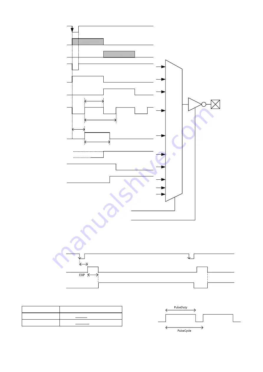
GPO output system diagram (example of GPO1)
Sensor readout (Sensor output)
When exposure finishes, this signal indicates that the image sensor is in the image output sequence. Output is available
from the GPO2/3 connectors. The sensor readout signal is asserted before the optical black (OB) and the effective pixel
area are output.
Pulse output
A pulse waveform can be output from the GPO2/3 connector. Available range is 0.5 Hz to 100 kHz.
Feature
Parameter
PulseDuty
1 to 500000 to 2000000 [µs]
PulseCycle
10 to 1000000 to 2000000 [µs]
0
1
0
1
Exposure
LineSource
Trigger signal
Sensor output
Trigger through signal
Sensor readout signal
Pulse output
Stro
b
e control signal
User definition 0
User definition 1
User definition 2
LineInverter
GPO2
GPO3
Exposure signal
Stro
b
eActiveDelay
Stro
b
eActiveTime
Trigger signal
Exposure signal
Sensor readout signal
(Sensor output)
Trigger latency


