1-5
UP-960(UC)
UP-960CE(CE)
36
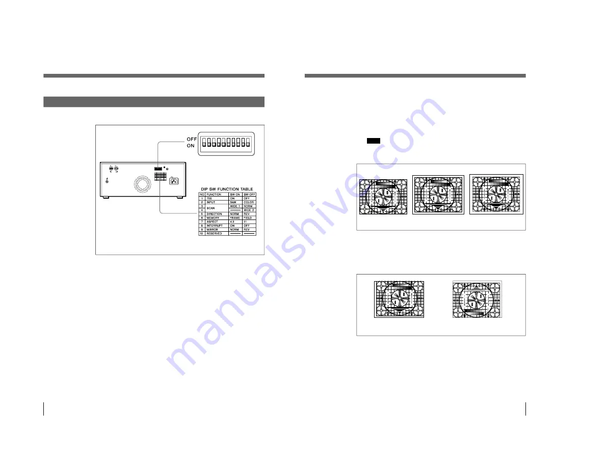
Setting the DIP Switches on the Rear Panel
The factory settings are as follows.
1
75
Ω
switch
ON (ON): When nothing is connected to the VIDEO OUT connector, set the
switch to this position.
OFF (OFF): When a video monitor or other video equipment is connected to
the VIDEO OUT connector, set the switch to this position.
When you connect two printers to one video equipment, set the 75
Ω
switch of
one of the printer to ON, and the other to OFF.
2
INPUT switch
B & W (ON): When the signal to be printed is black and white, set the switch
to this position.
COLOR (OFF): When the signal is color, set the switch to this position.
Preparation
Setting the DIP Switches (Continued)
REMOTE
AC IN
VIDEO
IN
OUT
ON
OFF
37
3
,
4
SCAN size switches
Set the printout range. The printout range is widened in the NORM, WIDE 1,
and WIDE 2 order.
NORM (Switch
3
: OFF): Prints only the image displayed on the standard
screen size of the video monitor.
WIDE 1(Switch
3
: ON): Prints when the signal scans beyond the edge of
the standard monitor screen.
WIDE 2 (Switch
4
: OFF): To further extend the range, select this setting.
Note
If the SCAN switch
4
is set to the OFF position (WIDE 2), WIDE 2 is
selected regardless of the setting of the SCAN switch
3
position.
5
DIRECTION switch
Selects whether the top or the bottom of the screen is to be printed first.
NORM (ON): Normally keep this switch set to this setting. Printing is done
from the bottom of the screen.
REV (OFF): Printing is started from the top of the screen.
6
MEMORY switch
FRAME (ON): Normally keep this switch set to this position.
FIELD (OFF): When printing fast moving pictures (such as a ball being
thrown), the printout may blur. If this happens, set to this position. The
printout definition will be poorer, but less blurred.
Preparation
30
3
2
2
3
3 4
3
4
1
3
5
5
3
1
1 3 5 7
7 5 3 1
5
3
1
30
3 2
2
3
3
4
3
4
30
3 2
2
3
3
4
3
4
3
2
3
3
4
4
3
2
5
3
1
30
275
8
7
6
5
4
3
2
1
475
50
250
9
4
5
5
7
5
4
3
3
2
3
2
30
10
7
0
3
30
3
2
2
3
34
3
4
1
3
5
5
3
1
1
3
5
7
7
5
3
1
5
3
1
30
3
2
2
3
3
4
3
4
30
3
2
2
3
3
4
3
4
3
2
3
3
4
4
3
2
5
3
1
30
275
8
7
6
5
4
3
2
1
475
50
250
9
4
5
5
7
5
4
3
3
2
3
2
30
10
7
0
3
NORM
REV
30
3
2
2
3
3 4
3
4
1
3
5
5
3
1
1 3 5 7
7 5 3 1
5
3
1
30
3 2
2
3
3
4
3
4
30
3 2
2
3
3
4
3
4
3
2
3
3
4
4
3
2
5
3
1
30
275
8
7
6
5
4
3
2
1
475
50
250
9
4
5
5
7
5
4
3
3
2
3
2
30
10
7
0
3
30
3
2
2
3
3 4
3
4
1
3
5
5
3
1
1 3 5 7
7 5 3 1
5
3
1
30
3 2
2
3
3
4
3
4
30
3 2
2
3
3
4
3
4
3
2
3
3
4
4
3
2
5
3
1
30
275
8
7
6
5
4
3
2
1
475
50
250
9
4
5
5
7
5
4
3
3
2
3
2
30
10
7
0
3
30
3
2
2
3
3 4
3
4
1
3
5
5
3
1
1 3 5 7
7 5 3 1
5
3
1
30
3 2
2
3
3
4
3
4
30
3 2
2
3
3
4
3
4
3
2
3
3
4
4
3
2
5
3
1
30
275
8
7
6
5
4
3
2
1
475
50
250
9
4
5
5
7
5
4
3
3
2
3
2
30
10
7
0
3
NORM
WIDE 1
WIDE 2
Summary of Contents for UP-960
Page 1: ...VIDEO GRAPHIC PRINTER UP 960 UP 960CE 1st Edition SERVICE MANUAL ...
Page 6: ......
Page 20: ......
Page 26: ......
Page 46: ......
Page 74: ......
Page 75: ...8 1 8 1 UP 960 UC UP 960CE CE SECTION 8 BLOCK DIAGRAMS ...
Page 92: ......


