SPP-A2480/S2430
– 45 –
– 46 –
4-7.
SCHEMATIC DIAGRAM – BASE MAIN Board (2/2) –
•
See page 38 for Waveforms.
• See page 55 for IC Block Diagram.
See page 37 for Note on Schematic Diagram.
(Page
44)
(Page 49)
Page 1: ...nsions Approx 58 x 185 4 x 48 mm w h d antenna excluded approx 2 3 8 x 7 3 8 x 1 15 16 inches Antenna Approx 72 mm approx 2 7 8 inches Mass Approx 260 g approx 9 2 oz battery included Base phone Power source DC 11V from AC power adaptor AC T107 Dimensions Approx 175 x 60 x 214 mm w h d antenna excluded approx 7 x 2 3 8 x 8 1 2 inches Antenna Approx 112 mm approx 4 1 2 inches Mass Approx 580 g appr...
Page 2: ...or Side BASE MIC Boards 41 4 6 Schematic Diagram BASE MAIN 1 2 BASE MIC Boards 43 4 7 Schematic Diagram BASE MAIN Board 2 2 45 4 8 Printed Wiring Boards BASE KEY KEY LED Boards 47 4 9 Schematic Diagram BASE KEY KEY LED Boards 49 4 10 Printed Wiring Board HAND MAIN Board 51 4 11 Schematic Diagram HAND MAIN Board 53 4 12 IC Pin Function Description 56 5 EXPLODED VIEWS 62 6 ELECTRICAL PARTS LIST 65 N...
Page 3: ... have call waiting service or lets you make a new call wg HOLD button p 30 Puts a call on hold wh MIC microphone p 54 65 wj Hook for AC power adaptor cord p 9 79 wk DIAL MODE switch p 10 Selects pulse or tone dialing wl DC IN 11V jack p 9 79 e LINE telephone line jack p 9 79 ea HANDSET jack p 9 Getting Started 24US 3 2 1 4 5 6 7 8 0 qh wa w ql qg qj qk ws wd wf qa qf qs qd 9 Identifying the parts ...
Page 4: ...2 Puts a call on hold wa MIC microphone ws Hook for AC power adaptor cord p 9 67 wd DIAL MODE switch p 10 Selects pulse or tone dialing wf DC IN 11V jack p 9 67 wg LINE telephone line jack p 9 67 wh HANDSET jack p 9 Getting Started 26US 3 2 1 4 5 6 7 8 qf qj qh qd qg qk ql w 9 qs 0 qa Identifying the parts continued 1 Antenna 2 Speaker EZfit p 30 3 Display window p 28 55 4 Jog Dial p 39 56 5 TALK ...
Page 5: ...he following steps Choose the best location Connect the base phone Choose the dialing mode Choose the best location Where you place the base phone affects the reception quality of the cordless handset Getting Started 10US Notes Use only the supplied AC T107 AC power adaptor Do not use any other AC power adaptor Connect the AC power adaptor to a continuous power supply Place the base phone close to...
Page 6: ...You hear a long confirmation beep Notes If the home area code is already entered it appears on the display in step 3 To enter a different home area code see To change the home area code below Do not allow more than 20 seconds to elapse during the operation procedure If the area code has not been entered calling back from the Caller ID list and storing the Caller ID data into the Phone Directory ca...
Page 7: ...e in the menu and by setting the long distance menu function to ACTIVE The long distance menu is preset to INACTIVE no preset access number is registered To set up the access number 1 Performsteps1and3onpage17 2 Turn Jog Dial to choose LONG DISTANCE and then pressJogButton ENTER 3 Turn Jog Dial to choose ACCESS NUMBER and then pressJogButton ENTER 4 Entertheaccessnumberusingthedialingkeys 5 Press ...
Page 8: ...en thephonestartscountingtime Notes Do not allow more than 60 seconds to elapse during the operation procedure SUN 12 00AM on the display of the base phone flashes when the day and time is cleared due to a power interruption or when you connect the base phone to the AC outlet for the first time If the current day and time are not set you will not hear a time stamp when you play back recorded messa...
Page 9: ...pprox 10 minutes PLEASE WAIT and BATTERY LOW appear on the display and the cordless handset cannot be used After BATTERY LOW turns off you may be able to use the cordless handset but the battery duration will be very short thus it is recommended that you fully charge the battery before next use Basics 29US Basics Making calls with the base phone Pick up the handset or press SPEAKERPHONE on the bas...
Page 10: ...NTER 4 Turn Jog Dial to choose ERASE REDIAL and then press Jog Dial or Jog Button ENTER You hear a long confirmation beep and the entire number are erased Basics 33US Basics 1 When you hear the phone ring Press TALK or Pick up the cordless handset from the charger when the cordless handset is placed on the charger When Quick talk is set to USE see page 34 TALK appears on the display and the displa...
Page 11: ...y pressing SPEAKERPHONE while talking over the handset 37US Telephone Features Telephone Features ONE TOUCH DIAL GO BACK ONE TOUCH A ONE TOUCH B ONE TOUCH C HANDSET MENU GO BACK PHONE DIRECTORY ONE TOUCH DIAL QUICK TALK One touch dialing You can dial with one touch of a key by storing a phone number on a one touch dialing button Storing phone numbers and names Example to store SONY 123 4567 1 Pres...
Page 12: ...e entry at one time Tips Single character and number can be erased by pressing ERASE in steps 2 and 4 You may press PROGRAM instead of doing steps 3 and 5 Making calls with one touch dialing 1 Press TALK or LONG DIST SAVER and wait until TALK appears on the display 2 Press one of the ONE TOUCH DIAL buttons A to C The phone number stored on the one touch dialing button will appear on the display an...
Page 13: ...ose DIAL or LONG DISTANCE and then press Jog Dial or Jog Button ENTER The phone number will be dialed Note When the Long Distance Saver function is set to ACTIVE LONG DISTANCE can be selected in step 4 see page 19 Tips When you select GO BACK you can return to the previous set display by pressing Jog Dial If you re at the base phone press Jog Button ENTER When you select CALLER ID in step 1 you ca...
Page 14: ...the base phone You can continue talking to the caller through the base phone TALK SPEAKERPHONE 49US Telephone Features Telephone Features Talking between the phones Intercom You can talk between the base phone and the cordless handset You can start the intercom from either phone To talk from the cordless handset to the base phone Press INTERCOM The base phone and cordless handset ring and PAGING a...
Page 15: ...n receive an intercom call on the base phone even when RINGER VOL on the base phone is set to OFF The base phone will ring at a low level OFF Transferring a call continued SPEAKERPHONE INTERCOM Answering Machine Features Answering Machine Features 53US Preparing the answering machine Answer settings can only be made on the base phone Note that you cannot operate the base phone while the cordless h...
Page 16: ...rom an outside phone and hear three rings you know that there are no new messages If you hang up at this point before the phone answers you can save the toll for the call 1 TIME to 4 TIMES The phone always answers at the set ring times and records incoming messages Note Do not allow more than 20 seconds to elapse during the operation procedure Tip When you select GO BACK you can return to the prev...
Page 17: ...es off Preparing the answering machine continued Answering Machine Features Answering Machine Features 61US TUE 4 53PM NEW MESSAGES 5 VIP 2 NEW CALLS 8 REC E F Playing back messages You can play back messages on both the base phone and the cordless handset When the phone is not in use and not in announcement only mode the display of the base phone shows the following When you come home If ANSWER O...
Page 18: ...et You can also answer the call by picking up the handset on another phone if it is connected to the same line TALK SPEAKERPHONE OFF Answering Machine Features Answering Machine Features 65US Recording a memo You can record a memo up to four minutes as a personal reminder or as a message for other people You can play back the recorded memo like any incoming messages see page 61 Memo recording is o...
Page 19: ... to call the extension About the memory match function The name stored in the one touch dialing or Phone Directory will appear on the display if you receive a call from a phone number which is stored on one of the ONE TOUCH DIAL buttons see page 37 or in the Phone Directory see page 41 In addition the ringer sound will change to a higher tone from the second ring and 9 will appear to the right of ...
Page 20: ...ot entered PLEASE ENTER AREA CODE will appear on the display and you will not be able to call back Enter the area code see page 13 Do not allow more than 20 seconds to elapse during the operation procedure If the number displayed in step 1 is not the one you should call back you can change the number of digits of the phone number as described on page 76 If the phone is connected to a Private Branc...
Page 21: ...Directory 1 While the phone number from the Caller ID list is displayed press repeatedly until the phone number with the correct number of digits appears on the display Each time you press the number of digits changes as follows When the home area code and the local area code do not match Using the Caller ID list continued Caller ID Features Caller ID Features 77US NEW 01 SMITH JOHN 201 123 4567 7...
Page 22: ... To go off the MESSAGES lamp 1 Press PROGRAM 2 Turn Jog Dial to choose BASE SETTINGS and then press Jog Button ENTER 3 Turn Jog Dial to choose MESSAGES LAMP and then press Jog Button ENTER 4 Press Jog Button ENTER The MESSAGES lamp on the base phone goes off and you hear a long confirmation beep continued MESSAGES lamp PROGRAM Jog Dial Jog Button ENTER 66US Caller ID Features If you move or change...
Page 23: ...r battery assy in the direction of arrow A A 2 two screws BTP2 6 12 4 claw 3 two claws 5 Remove the cabinet rear in the direction of arrow B B Set Cabinet Rear Hand Main Board Antenna Hand Assy ANT201 Base Cabinet Upper Assy Base Main Board Base MIC Board Base Key Board This set can be disassembled in the order shown below ...
Page 24: ...four screws P3 10 3 connector CN302 3 connector CN301 2 HAND MAIN BOARD ANTENNA HAND ASSY ANT201 6 two screws BTP2 6 8 7 cover head set 8 terminal hand 9 2 screw BTP2 6 12 3 washer fiber 4 spacer mic 1 connector CN1 qa HAND MAIN board 0 button VOL H 5 antenna hand assy ANT201 ...
Page 25: ...two screws BTP2 6 8 2 four screws BTP2 6 8 2 two screws BTP2 6 8 3 BASE KEY board BASE MAIN BOARD BASE MIC BOARD 2 BASE MIC board 3 three screws BTP2 6 8 3 screw BTP2 6 8 5 BASE MAIN board 4 clamp 1 Remove two solders lead of antenna ...
Page 26: ...T A state press the key Turn the power off Key Matrix Test Mode 1 In the TEST A state press the 1 key and this test mode will become active 2 In this test mode press the following keys in the given order and an acknowledged tone will be generated from the speaker and LCD back light LEDs will light up If the keys are pressed in unspecified order an error tone is generated from the speaker and the b...
Page 27: ...ode 1 Turn the power on LCD displays PLEASE WAIT for about 5 sec 2 With the set in idle on hook state press ERASE LONG DIST SAVER 2 keys at a time 3 When the test mode becomes active the LCD displays TEST B ID along with an acknowledged tone and the base unit waits for a command 4 After the test mode becomes active the ID writing mode be comes active and current ID is displayed To write the ID ent...
Page 28: ... 3rd byte LQ alarm diversity ANT threshold 00h LINEVOL Addr F4Ch C4h C6h 00h CSUM 75h Contents of Setting Default Value 1st byte LINE VOL of speakerphone C4h intercom path 2nd byte LINE VOL of speakerphone C6h outside line path 3rd byte N A 00h SPP VOL Addr F50h 06h 00h 00h CSUM F9h Contents of Setting Default Value 1st byte SP VOLT of speakerphone intercom 06h path MAX for main 2nd byte LOOP ATT ...
Page 29: ...d the handset returns to the initial test mode TEST A and waits for a command Jog dial RING on off switch Test Mode 1 In the TEST A state press the 2 key and this test mode will become active 2 In this test mode rotate the jog dial clockwise or counterclock wise press the button turn on off the RING switch and re spective states will be displayed on the LCD Switch Name Operation LCD Display Clockw...
Page 30: ... 0003B4 TX RX 18ch ID 0004B4h TX RX 23ch ID 0005B4 TX RX 27ch ID 0006B4h TX RX 7ch ID 0007B4 TX RX 12ch ID 0008B4h TX RX 15ch ID 0009B4 TX RX 24ch ID 000AB4h TX RX 8ch ID 000BB4 TX RX 16ch ID 000CB4h TX RX 25ch ID 000DB4 TX RX 9ch ID 000EB4h TX RX 17ch ID 000FB4 TX RX 26ch 5 In the TEST C command input waiting state pressing the following keys allows the associated mode to become active 1 TX power...
Page 31: ...operation you can cancel the operation and retry from the beginning 7 The EEPROM addresses and parameters of the handset are listed below LXT821 Addr 6D8h 9Fh 1Ah 02h CSUM 44h Contents of Setting Default Value 1st byte AMUTE Addr 10h LXT821 AMC 9fh 2nd byte Div TX power switching threshold RSSI 1Ah 3rd byte TX power reduction threshold RSSI 02h LXT821 REGISTER SETTING VALUE 1 20 bytes of the addre...
Page 32: ...NT RING DET TEL LINE B ANSWER ON OFF LED DRIVE Q711 D711 D712 D721 726 LCD BACK LIGHT HOOK SW DET JOG PUSH JOG B JOG A E2PROM SCL E2PROM SDA SCL SDA LCD SDA LCD SCL LCD CS SDA SCL CS RESET LED CONT LCD SYSTEM CONTROLLER IC251 RESET LCD101 LIQUID CRYSTAL DISPLAY MODULE S251 HOOK ON OFF 5V B JOG701 JOG SS SPI DIN SS SPI DOUT SS SPI CLK SS PWR DOWN CONT ANTENNA SELECT B ANTENNA SELECT A SS IRQ SS SPI...
Page 33: ...SDA LCD SCL LCD CS LCD CONTROL RESET LED CONT LCD LED CONT KEY SS POWER CONT STAND BY SS POWER CONT TALK DIS CHG WAKE UP WAKE UP LOW BAT DET CHARGE DET BATT POWER FAIL RESET SP1 SPEAKER MIC1 MIC BZ1 BUZZER SDA SCL CS VCI LCD201 LIQUID CRYSTAL DISPLAY MODULE 3 3V B RESET SIGNAL GENERATOR IC53 CHARGE ON DETECT Q107 3 3V REGULATOR IC101 Q108 VOLTAGE DETECT IC102 CHARGE ON DETECT Q106 LED DRIVE Q52 LE...
Page 34: ...mpedance 10 MΩ Voltage variations may be noted due to normal produc tion tolerances Waveforms are taken with a oscilloscope Voltage variations may be noted due to normal produc tion tolerances Circled numbers refer to waveforms Signal path N RX O TX P BELL Note on Printed Wiring Board X parts extracted from the component side Y parts extracted from the conductor side a Through hole Pattern from th...
Page 35: ...1 RF UNIT 10 24 1 3 S2430 C629 C627 C628 JC604 L602 C626 C230 BASE MAIN BOARD COMPONENT SIDE ANT102 SUB ANTENNA ANT101 MAIN ANTENNA 05 B C D E F G H I J K 1 2 3 4 5 6 7 8 9 10 11 12 13 14 A Semiconductor Location Ref No Location IC231 I 8 IC232 I 8 IC251 I 4 IC252 K 3 IC253 H 6 IC471 C 7 IC651 E 4 IC671 F 3 Q231 H 7 Q251 J 5 Q403 D 8 Q405 D 8 Q406 D 7 Q471 B 7 Q472 B 7 Q473 C 9 Q474 C 8 ...
Page 36: ...4 B BASE KEY BOARD CN305 1 2 BASE MIC BOARD COMPONENT SIDE MIC401 MIC BASE MIC BOARD CONDUCTOR SIDE 1 2 05 B C D E F G H I J K 1 2 3 4 5 6 7 8 9 10 11 12 13 14 15 16 A 41 42 4 5 PRINTED WIRING BOARDS BASE MAIN Conductor Side BASE MIC Boards See page 37 for Note on Printed Wiring Board Semiconductor Location Ref No Location D251 I 9 D252 J 8 D401 E 4 D402 E 5 D403 E 4 D404 E 4 D405 D 5 D501 G 3 D50...
Page 37: ...SPP A2480 S2430 43 44 4 6 SCHEMATIC DIAGRAM BASE MAIN 1 2 BASE MIC Boards See page 37 for Note on Schematic Diagram Page 45 ...
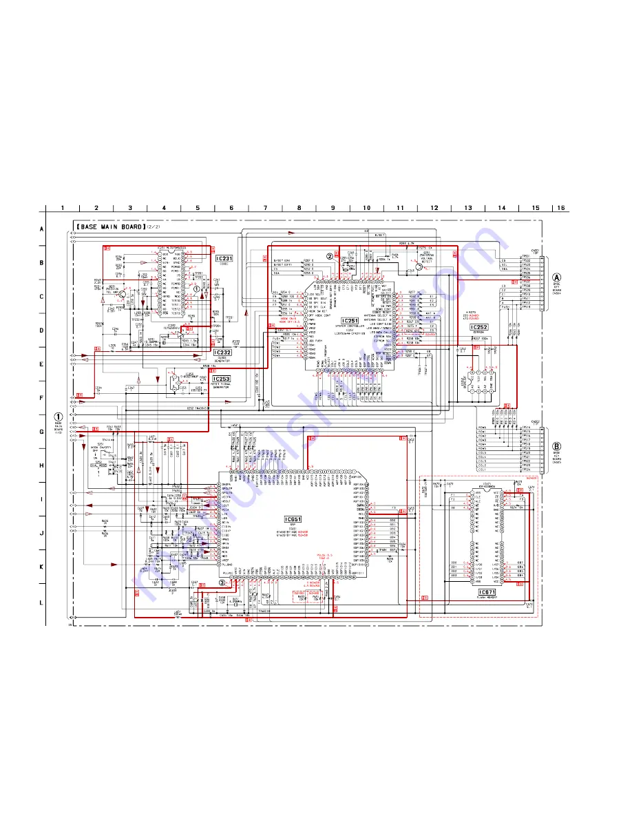
Page 38: ...SPP A2480 S2430 45 46 4 7 SCHEMATIC DIAGRAM BASE MAIN Board 2 2 See page 38 for Waveforms See page 55 for IC Block Diagram See page 37 for Note on Schematic Diagram Page 44 Page 49 Page 49 ...
Page 39: ...0 PROGRAM K729 ERASE K728 VOLUME K727 VOLUME K719 REDIAL PAUSE K709 CALL WAITING FLASH K714 INTERCOM K704 HOLD K721 MEMO D713 MESSAGES K716 K711 K722 PLAY STOP D712 NEW CALL K717 ABC 2 K712 JKL 5 D711 K723 ANSWER ON OFF K718 K713 K723 K706 K707 TUV 8 K708 WXYZ 9 PQRS 7 K701 K702 OPER 0 K703 TONE K720 SPEAKERPHONE K705 LONG DIST SAVER D711 713 K718 REPEAT 1 K716 DEF SKIP 3 K713 GHI REVIEW 4 K711 MN...
Page 40: ...SPP A2480 S2430 49 50 4 9 SCHEMATIC DIAGRAM BASE KEY KEY LED Boards See page 37 for Note on Schematic Diagram Page 46 Page 46 ...
Page 41: ...r OFF RECHARGEABLE BATTERY PACK BP T24 3 6V 1000mAh D52 55 K706 REPEAT 1 K726 SKIP 3 DEF K709 REVIEW 4 GHI K714 PLAY BACK HOLD 1 3 DEF 4 GHI K727 QUICK 6 MNO 6 MNO HOLD A2480 S2430 KEY BACK LIGHT BLK RED HAND MAIN BOARD CONDUCTOR SIDE 05 B C D E F G H I 1 2 3 4 5 6 7 8 9 10 11 12 13 14 15 A 51 52 4 10 PRINTED WIRING BOARD HAND MAIN Board See page 37 for Note on Printed Wiring Board IC53 B 9 IC101 ...
Page 42: ...SPP A2480 S2430 53 54 4 11 SCHEMATIC DIAGRAM HAND MAIN Board See page 38 for Waveforms See page 55 for IC Block Diagrams See page 37 for Note on Schematic Diagram C127 1 ...
Page 43: ...the rotary encoder JOG701 A phase input 23 JOG B I Jog dial pulse input of the rotary encoder JOG701 B phase input 24 to 26 COL3 to COL5 O Key scan output to the key matrix L output when key waiting 27 DSP SC O Serial data transfer clock signal output to the DSP IC651 28 DSP HRNW O Data read write selection signal output to the DSP IC651 L data write H data read 29 DSP CSN O Chip select signal out...
Page 44: ...eset For several hundreds msec after the power supply rises L is input then it changes to H 54 XT1 I Sub system clock input terminal 32 768 kHz Not used fixed at H 55 XT2 O Sub system clock output terminal 32 768 kHz Not used open 56 VSS1 Ground terminal 57 CF1 I Main system clock input terminal 6 MHz 58 CF2 O Main system clock output terminal 6 MHz 59 VDD1 Power supply terminal 5V 60 BRANCH DET O...
Page 45: ... signal 40 DCIN I Not used open 41 CIDIN I Caller ID detection signal input terminal 42 CIDIP I Caller ID detection signal input terminal 43 CIDO O Feedback output of caller ID detection input signal 44 HMGS O Feedback output of receive data input signal 45 HMIN I Receive data input from the CODEC IC231 46 GNDA Ground terminal 47 MIN I Analog audio signal input from the microphone 48 MGS O Feedbac...
Page 46: ...2 input terminal L T tone H P pulse 74 GND Ground terminal 75 VCC Power supply terminal 5V 76 to 82 DGPIO15 to DGPIO9 I O Not used open 83 DGPIO8 I O Not used pull up 84 to 91 DGPIO7 to DGPIO0 I O Two way data bus with the flash memory IC671 Used for the SPP A2480 model 92 GND Ground terminal 93 VCC Power supply terminal 5V 94 DRDN O Read enable signal output to the flash memory IC671 L active Use...
Page 47: ...key waiting 27 SP AMP POWER CONT O Power on off control signal output for speaker amplifier L power on 28 SS POWER CONT STAND BY O Power on off control signal output for RF unit RF1 at the stand by L half power on 29 SS POWER CONT TALK O Power on off control signal output for RF unit RF1 at the talk L full power on 30 BUZZER VOL O Buzzer sound level control signal output L low level 31 LOW BAT DET...
Page 48: ... IC53 L reset For several hundreds msec after the power supply rises L is input then it changes to H 54 XT1 I Sub system clock input terminal 32 768 kHz Not used fixed at H 55 XT2 O Sub system clock output terminal 32 768 kHz Not used open 56 VSS1 Ground terminal 57 CF1 I Main system clock input terminal 6 MHz 58 CF2 O Main system clock output terminal 6 MHz 59 VDD1 Power supply terminal 3 3V 60 A...
Page 49: ...art No Description Remark Ref No Part No Description Remark 1 1 771 923 21 SWITCH RUBBER KEY HAND 2 3 044 764 21 CABINET FRONT A2480 2 3 044 764 31 CABINET FRONT S2430 3 3 044 767 11 PANEL HAND SET 4 3 044 773 01 COVER HEAD SET JACK 5 3 044 768 11 PAD EAR 6 3 049 513 01 COVER RECEIVER 7 X 3378 848 1 HINGE ASSY 8 3 040 204 01 SPACER FLEXIBLE 9 3 034 810 01 SPRING LEAF 10 3 044 769 01 HOLDER LCD H 1...
Page 50: ...T UPPER 59 3 044 798 11 LEVER HOOK 60 3 048 089 11 HOLDER HAND SET 61 3 223 993 01 PANEL 62 3 223 995 01 BUTTON P E 63 1 771 925 11 SWITCH RUBBER KEY 2 GANG 64 3 044 789 01 DIAL JOG 65 3 044 795 11 BUTTON VOL 66 3 044 796 01 BUTTON ANS 67 3 015 461 01 BRACKET SP STOPPER 68 3 044 797 11 BUTTON 12 KEY 69 1 771 924 11 SWITCH RUBBER KEY 1BASE 71 3 044 793 01 BUTTON JOG 72 3 044 800 01 SHEET DIFFUSION ...
Page 51: ... 461 01 BRACKET SP STOPPER 118 3 044 797 11 BUTTON 12 KEY 119 1 786 038 11 SWITCH RUBBER KEY BASE 121 3 044 793 01 BUTTON JOG 122 3 044 800 01 SHEET DIFFUSION 123 3 044 788 01 HOLDER LCD 124 3 044 799 01 SPRING JOG 125 A 3062 287 A BASE KEY BOARD COMPLETE including KEY LED BOARD 126 3 037 081 01 PLUG ANTENNA 127 3 224 690 01 SHEET PANEL ADHESIVE 128 3 701 748 00 CLAMP ANT101 1 754 164 11 ANTENNA A...
Page 52: ...L CHIP 330 5 1 16W R702 1 216 849 11 METAL CHIP 220K 5 1 16W R703 1 216 849 11 METAL CHIP 220K 5 1 16W R704 1 216 864 11 METAL CHIP 0 5 1 16W R705 1 216 864 11 METAL CHIP 0 5 1 16W R706 1 216 864 91 SHORT 0 R707 1 216 833 11 METAL CHIP 10K 5 1 16W R711 1 216 793 11 RES CHIP 4 7 5 1 16W R712 1 216 845 11 METAL CHIP 100K 5 1 16W R713 1 216 864 11 METAL CHIP 0 5 1 16W S2430 SWITCH S701 1 570 909 21 S...
Page 53: ...C512 1 164 005 11 CERAMIC CHIP 0 47uF 25V C513 1 164 005 11 CERAMIC CHIP 0 47uF 25V C514 1 162 908 11 CERAMIC CHIP 3PF 0 25PF 50V C601 1 164 360 11 CERAMIC CHIP 0 1uF 16V C602 1 164 360 11 CERAMIC CHIP 0 1uF 16V C603 1 162 960 11 CERAMIC CHIP 220PF 10 50V C604 1 162 908 11 CERAMIC CHIP 3PF 0 25PF 50V C605 1 162 961 11 CERAMIC CHIP 330PF 10 50V C606 1 162 921 11 CERAMIC CHIP 33PF 5 50V C607 1 125 8...
Page 54: ... METAL CHIP 0 5 1 16W L651 1 408 621 31 INDUCTOR 330uH L653 1 216 864 11 METAL CHIP 0 5 1 16W PHOTO COUPLER PH401 8 749 015 01 PHOTO COUPLER 5817P6 TRANSISTOR Q231 8 729 120 28 TRANSISTOR 2SC1623 L5L6 Q251 8 729 026 49 TRANSISTOR 2SA1037AK T146 R Q402 8 729 045 65 TRANSISTOR 2SA1776TV2Q Q403 8 729 920 85 TRANSISTOR 2SD1664 QR Q404 8 729 045 47 TRANSISTOR 2SC4620TV2Q Q405 8 729 026 49 TRANSISTOR 2S...
Page 55: ...414 1 215 863 11 METAL OXIDE 100 5 1W F R415 1 216 817 11 METAL CHIP 470 5 1 16W R416 1 216 813 11 METAL CHIP 220 5 1 16W R417 1 216 833 11 METAL CHIP 10K 5 1 16W R418 1 216 825 11 METAL CHIP 2 2K 5 1 16W R419 1 249 417 11 CARBON 1K 5 1 4W R420 1 216 833 11 METAL CHIP 10K 5 1 16W R421 1 216 864 11 METAL CHIP 0 5 1 16W R422 1 216 813 11 METAL CHIP 220 5 1 16W R423 1 216 828 11 METAL CHIP 3 9K 5 1 1...
Page 56: ...C47 1 164 360 11 CERAMIC CHIP 0 1uF 16V C48 1 115 156 11 CERAMIC CHIP 1uF 10V C49 1 162 927 11 CERAMIC CHIP 100PF 5 50V C50 1 164 360 11 CERAMIC CHIP 0 1uF 16V C51 1 164 360 11 CERAMIC CHIP 0 1uF 16V C52 1 164 360 11 CERAMIC CHIP 0 1uF 16V C53 1 125 837 11 CERAMIC CHIP 1uF 10 6 3V C54 1 164 360 11 CERAMIC CHIP 0 1uF 16V C55 1 127 573 11 CERAMIC CHIP 1uF 10 16V C56 1 127 573 11 CERAMIC CHIP 1uF 10 ...
Page 57: ...NSISTOR Q1 8 729 230 72 TRANSISTOR 2SA1362YG Q2 8 729 026 49 TRANSISTOR 2SA1037AK T146 R Q31 8 729 230 72 TRANSISTOR 2SA1362YG Q32 8 729 120 28 TRANSISTOR 2SC1623 L5L6 Q51 8 729 026 49 TRANSISTOR 2SA1037AK T146 R Q52 8 729 026 49 TRANSISTOR 2SA1037AK T146 R Q101 8 729 120 28 TRANSISTOR 2SC1623 L5L6 Q102 8 729 026 49 TRANSISTOR 2SA1037AK T146 R Q103 8 729 120 28 TRANSISTOR 2SC1623 L5L6 Q104 8 729 1...
Page 58: ...16W R112 1 216 864 11 METAL CHIP 0 5 1 16W R114 1 218 891 11 METAL CHIP 68K 0 5 1 16W R115 1 218 917 11 METAL CHIP 820K 0 5 1 16W R116 1 216 829 11 METAL CHIP 4 7K 5 1 16W R117 1 216 829 11 METAL CHIP 4 7K 5 1 16W R118 1 216 845 11 METAL CHIP 100K 5 1 16W R119 1 216 833 11 METAL CHIP 10K 5 1 16W R120 1 216 845 11 METAL CHIP 100K 5 1 16W R121 1 216 808 11 METAL CHIP 82 5 1 16W R122 1 216 797 11 MET...
Page 59: ...CREW BTP 2 6X12 TYPE2 N S 3 7 685 533 19 SCREW BTP 2 6X6 TYPE2 N S 5 7 685 647 79 SCREW P 3X10 TYPE2 NON SLIT ACCESSORIES PACKING MATERIALS X 3380 011 1 HAND ASSY LOCAL 0 X 3380 503 1 PLATE ASSY SVX CHARGE 0 1 476 240 11 ADAPTOR AC AC T107 1 528 884 41 BATTERY NICKEL CADMIUM BP T24 1 543 584 31 CORE 1 696 453 21 CORD WITH MODULAR PLUG LINE 22cm 1 696 454 11 CORD WITH MODULAR PLUG LINE 215cm 1 791 ...