background image

2-11

SEL1655G

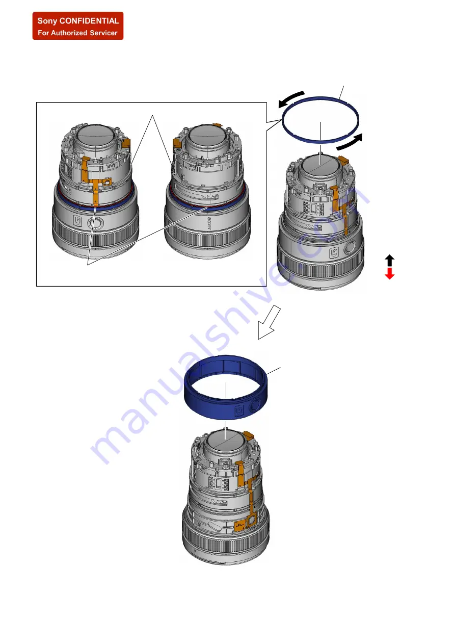
2-2-12. MID  COVER  ASSY

rear (mount) side

front (lens) side

1

 Pour alcohol into the gap between the mid cover stopper 


and STA barrel assy.

STA barrel assy

2

 Remove by rotating the mid cover stopper 


in the direction of the arrow.

3

 mid cover assy


Note:

 Take care not to damage 


the flexible board.

SYS SET

2020/02/04 22:49:28 (GMT+09:00)

Summary of Contents for SEL1655G

Page 1: ...dition to the above the terms and conditions of the Service agreement shall be applied to using this information Revision of Information This information may be changed or updated at any time without any prior notice Please confirm that this information is up to date before using it US Model Canadian Model AEP Model Chinese Model INTERCHANGEABLE LENS 2020 01 2020A33 1 9 896 861 12 Ver 1 1 2020 01 S...

Page 2: ...sed for unleaded solder and those for leaded solder so they are managed separately Mixing unleaded solder and leaded solder will cause detach ment phenomenon ᝅ 如果电池更换不当会有爆炸危险 只能用同样类型或等效类型的电池来更换 务必按照说明处置用完的电池 1 4 SAFETY CHECK OUT After correcting the original service problem perform the following safety checks before releasing the set to the customer 1 Check the area of your repair for unsoldered o...

Page 3: ...adjustment program SEL1655G_ Service_Tool is set to Read to implement the AjustData Backup After main board replacement Read Write Select of Lens adjustment program SEL1655G_ Service_Tool is set to Write to implement the AjustData Backup If the adjustment data can not be read from the main board before replacement perform Serial Write of Lens adjustment program SEL1655G_Service_Tool after the main...

Page 4: ...sing the connector s holder press it evenly while pushing a flexible board in direction B Holder Connector Flexible Board A A Holder Insulation side Connector Flexible Board B Make sure that the flat cable and flexible board are not cracked or bent at the contact end Do not apply excessive force to the gilded flexible board Cut and remove the part of gilt which comes off at the point Be careful or...

Page 5: ... cover stopper appearance block guard tape Z focus ring rubber B focus ring assy STA barrel assy focus ring key focus ring key focus ring key focus ring key focus ring key focus ring key 6th group assy cam follower A cam follower A cam follower A cam follower A cam follower A cam follower A iris iris cover gom bush B gom bush B main FPC plate 3 5 group assy cam pin shaft M cam pin shaft M cam pin ...

Page 6: ... 9 2 2 11 ZOOM RING ASSY Page 2 10 2 2 12 MID COVER ASSY Page 2 11 2 2 13 APPEARANCE BLOCK Page 2 12 2 2 15 FOCUS RING ASSY Page 2 13 2 2 16 6TH GROUP ASSY Page 2 14 2 2 17 3 5 GROUP BLOCK Page 2 15 2 2 20 2ND LENS BARREL ASSY Z CAM BAR ASSY Page 2 18 2 2 18 IRIS 3 5 GROUP ASSY Page 2 16 2 2 19 1ST MOVING FRAME ASSY Page 2 17 2 2 14 FOCUS RING RUBBER B Page 2 12 2 2 8 TORQUE ADJUST PLATE BLOCK Pag...

Page 7: ...ol ornament plate repair tape Note 1 Remove the ornament plate using the service tool Front ring remover J 6082 860 A Sectional view 3 Lift the service tool to the front outer assy side Note 3 Be careful not to scratch the front outer assy 2 Put the tip of the service tool between the concavity position of the ornament plate and the front outer assy Note 2 Be careful not to scratch the ornament pl...

Page 8: ...ent washers Note Take note of the amount of washers 2 2 3 FRONT OUTER ASSY rear mount side front lens side screw position boss screw position 1 three tapping screws 1 4 u 4 2 front outer assy 1 three tapping screws 1 4 u 4 front outer assy from front lens side Note Take care not to damage the boss SYS SET 2020 02 04 22 49 28 GMT 09 00 ...

Page 9: ...unt block mount rubber three C tapes Note 4 C tapes cannot be reused Be sure to replace them with new parts 7 ring click2 spring 7 ring click2 spring 6 M pin A 6 M pin A 3 contact flexible board 4 mount assy 1 four tapping screws 2 u 8 7KH PRXQW DVV FDQ EH GLVDVVHPEOHG DV VKRZQ LQ WKH ILJXUH EHORZ 2 Lift up the mount assy Note 1 Take care not to damage the flexible board Note 2 Take care not to lo...

Page 10: ...ubber 1 four tapping screws 1 4 u 3 torque adjust sheet 7KH WRUTXH DGMXVW SODWH EORFN FDQ EH GLVDVVHPEOHG DV VKRZQ LQ WKH ILJXUH EHORZ 2 2 7 REAR COVER ASSY rear mount side front lens side 1 four tapping screws 1 7 u 5 screw position screw position 2 rear cover assy rear cover assy from rear mount side SYS SET 2020 02 04 22 49 28 GMT 09 00 ...

Page 11: ... side 1 two tapping screws 1 4 u 2 3 two tapping screws 1 4 u 3 5 4 ZMR assy ZMR holder part Note Take care not to damage the flexible board 2 ZMR assy potentiometer part Note Take care not to damage the flexible board SYS SET 2020 02 04 22 49 28 GMT 09 00 ...

Page 12: ...2 9 SEL1655G 2 2 10 ZOOM RING RUBBER B rear mount side front lens side 3 guard tape Z 2 FPC repair tape A 7 7 1 zoom ring rubber B SYS SET 2020 02 04 22 49 28 GMT 09 00 ...

Page 13: ... 1 cam pin A 2 Rotate the zoom ring assy in the direction of the arrow from the hole to the position where you can see the zoom linkage pin 1 cam pin A 3 two zoom linkage pin blocks 7KH RRP OLQNDJH SLQ EORFN FDQ EH GLVDVVHPEOHG DV VKRZQ LQ WKH ILJXUH EHORZ zoom linkage pin zoom linkage pin cam follower A M convex part notch zoom ring assy from rear mount side SYS SET 2020 02 04 22 49 28 GMT 09 00 ...

Page 14: ...1 Pour alcohol into the gap between the mid cover stopper and STA barrel assy STA barrel assy 2 Remove by rotating the mid cover stopper in the direction of the arrow 3 mid cover assy Note Take care not to damage the flexible board SYS SET 2020 02 04 22 49 28 GMT 09 00 ...

Page 15: ...ree screws M1 7 u 3 5 screw position appearance block from rear mount side 2 appearance block Note Take care not to damage the flexible board 2 2 14 FOCUS RING RUBBER B rear mount side front lens side 2 guard tape Z 1 focus ring rubber B SYS SET 2020 02 04 22 49 28 GMT 09 00 ...

Page 16: ...ssy 4 focus ring assy 5 STA barrel assy 2 tapping screw 1 4 u 2 5 2 tapping screw 1 4 u 2 5 2 tapping screw 1 4 u 2 5 2 tapping screw 1 4 u 2 5 2 tapping screw 1 4 u 2 5 2 tapping screw 1 4 u 2 5 3 focus ring key 3 focus ring key 3 focus ring key 3 focus ring key 3 focus ring key 3 focus ring key focus ring assy SYS SET 2020 02 04 22 49 28 GMT 09 00 ...

Page 17: ...655G 2 2 16 6TH GROUP ASSY rear mount side front lens side 3 three back adjustment washers Note Take note of the amount of washers 1 three screws M1 7 u 3 5 2 6th group assy SYS SET 2020 02 04 22 49 28 GMT 09 00 ...

Page 18: ...OUP BLOCK rear mount side front lens side 2 Lift up the main FPC plate 3 cam pin 3 cam pin 3 cam pin 5 3 5 group block 4 cam follower A 4 cam follower A 4 cam follower A 1 two screws M1 4 u 3 SYS SET 2020 02 04 22 49 28 GMT 09 00 ...

Page 19: ...the FPC repair tape A 7 7 off from the main FPC plate 9 main FPC plate 5 Draw the iris flexible board out of the hole Note 1 Take care not to damage the flexible board 7 three gom bushs B Note 2 The gom bush B may be stuck to iris Take care not to lose the gom bush B Note 3 Take care not to damage the boss 0 3 5 group assy SYS SET 2020 02 04 22 49 28 GMT 09 00 ...

Page 20: ...ens side cam follower A M cam pin shaft M 3 cam pin shaft M block 3 two cam pin shaft M blocks 2 1st moving frame assy 1 cam pin A 1 cam pin A 1 cam pin A 7KH FDP SLQ VKDIW 0 EORFN FDQ EH GLVDVVHPEOHG DV VKRZQ LQ WKH ILJXUH EHORZ SYS SET 2020 02 04 22 49 28 GMT 09 00 ...

Page 21: ... barrel assy from rear mount side G7 mask 2nd shading sheet 7KH FDP EDU EORFN FDQ EH GLVDVVHPEOHG DV VKRZQ LQ WKH ILJXUH EHORZ ZM straight 2G mask Note 2 Do not remove unless necessary to replace Be careful not to get scratches or dirt cam pin I_A cam pin I_A cam pin I_A Z cam bar assy cam follower I_A 4 0 cam follower I_A 4 0 cam follower I_A 4 0 Note 1 The 2nd shading sheet and the G7 mask can n...

Page 22: ...Page 2 33 2 3 15 ZOOM RING RUBBER B Page 2 32 2 3 13 ZOOM RING ASSY Page 2 30 2 3 14 ZOOM LINKAGE PIN Page 2 31 2 3 12 MID COVER ASSY Page 2 29 2 3 11 APPEARANCE BLOCK Page 2 28 2 3 9 FOCUS RING ASSY Page 2 27 2 3 8 6TH GROUP ASSY Page 2 26 2 3 7 3 5 GROUP BLOCK Page 2 25 2 3 2 CAM FOLLOWER I_A 4 0 ZM STRAIGHT 2G MASK Page 2 20 2 3 3 2ND LENS BARREL ASSY Page 2 21 2 3 4 1ST MOVING FRAME ASSY Page ...

Page 23: ...owers I_A 4 0 Note 1 When replacing the cam follower I_A 4 0 choose parts that do not cause backlash and confirm that movement is smooth 4 Paste the ZM straight 2G mask to the outline of Z cam bar assy Note 2 After installing the 2nd lens barrel assy etc check the operation and make sure that the ZM straight 2G mask is not in contact or abnormal noise is generated 3 cam pin I_A 1 P 3 cam pin I_A 1...

Page 24: ...rel assy from front lens side 2nd lens barrel assy from rear mount side G7 mask 2nd shading sheet 4 cam follower A Note 2 When replacing the cam follower A choose parts that do not cause backlash and confirm that movement is smooth 4 cam follower A Note 2 When replacing the cam follower A choose parts that do not cause backlash and confirm that movement is smooth 4 cam follower A Note 2 When repla...

Page 25: ...cklash and confirm that movement is smooth 3 three cam pin shafts M 4 cam pin shaft M block 4 cam pin shaft M block 4 cam pin shaft M block cam pin shaft M Note 2 Install the cam pin shaft M as shown in the direction of figure below 6 Align the groove the Z cam bar block with the marking of the 1st moving frame assy and install the Z cam bar block marking 5 1st moving frame assy groove Z cam bar b...

Page 26: ... the valley of the main flexible board into the main FPC plate 1 3 5 group assy Note 1 A protective part iris cover and part of 6th lens assy is attached When replacing remove them before use Note 2 Take care not to damage the boss 6 Paste the main FPC plate to the FPC repair tape A 7 7 Note 3 Make sure that the main flexible board is not floated up SYS SET 2020 02 04 22 49 28 GMT 09 00 ...

Page 27: ... boss 1 Install the gom bush B to the boss 1 Install the gom bush B to the boss 5 Install the iris 4 boss 4 boss 6 iris cover 7 two claws 7 claw 3 Pass the iris flexible board through the hole Note Take care not to damage the flexible board 8 Connect the iris flexible board SYS SET 2020 02 04 22 49 28 GMT 09 00 ...

Page 28: ...4 Insert the 3 5 group block to the position shown below screw hole 2 Set the lever in the direction of the arrow lever groove 5 three cam followers A Note When replacing the cam follower A choose parts that do not cause backlash and confirm that movement is smooth 8 two screws M1 4 u 3 1 P 9 adhesive bond 2 places 1 Align the groove on the Z cam bar block groove small groove small groove large SY...

Page 29: ...7 u 3 5 4 Tighten the three screws M1 7 u 3 5 1 P QVWDOODWLRQ GLUHFWLRQ IRU WKH EDFN DGMXVWPHQW ZDVKHU 1 6th group assy 3 three back adjustment washers Note 1 Install exactly as recorded during disassembly 5 Fix the three screws with adhesive bonds Note 2 Apply adhesive bond coating after adjustment 6th group assy from rear mount side SYS SET 2020 02 04 22 49 28 GMT 09 00 ...

Page 30: ...s ring key focus ring key focus ring key focus ring key focus ring key focus ring assy rear mount side front lens side convex part convex part outer side inner side 4 focus ring key total six pieces Note Be careful of the direction of installation 5 boss 5 boss 6 tapping screw 1 4 u 2 5 total six pieces 1 P rear mount side front lens side convex part convex part outer side inner side 4 focus ring ...

Page 31: ...lock guard tape Z 2 3 11 APPEARANCE BLOCK B 10 B 10 rear mount side front lens side 1 Install the appearance block in the position shown in the figure Note Take care so that the flexible board is not pinched 2 three screws M1 7 u 3 5 1 P 3 Fix the three screws with adhesive bonds button part index 90 appearance block from rear mount side SYS SET 2020 02 04 22 49 28 GMT 09 00 ...

Page 32: ...mid cover assy Note Take care so that the flexible board is not pinched 3 Install by rotating the mid cover stopper in the direction of the arrow 2 Apply adhesive bond to two points on the diagonal of the mid cover assy cutout cutout button part mid cover stopper mid cover assy QVWDOODWLRQ GLUHFWLRQ IRU WKH PLG FRYHU VWRSSHU SYS SET 2020 02 04 22 49 28 GMT 09 00 ...

Page 33: ...hree convex parts with the three notches to install the zoom ring assy Note Take care not to damage the flexible board 1 Apply grease to 3 places all around of the STA barrel assy convex part notch zoom ring assy from rear mount side STA barrel assy SYS SET 2020 02 04 22 49 28 GMT 09 00 ...

Page 34: ...on of the arrow and align the screw holes screw hole zoom ring assy zoom ring assy hole 55 G badge cam groove 2 two cam followers A M Note 1 When replacing the cam follower A M choose parts that do not cause backlash and confirm that movement is smooth 3 two zoom linkage pins Note 2 Install the zoom linkage pin as shown in the direction of figure below zoom linkage pin 6 cam pin A 1 P 6 cam pin A ...

Page 35: ...M RING RUBBER B rear mount side front lens side 3DVWLQJ SRVLWLRQ RI WKH JXDUG WDSH 1 guard tape Z pasting reference guard tape Z zoom ring assy 2 FPC repair tape A 7 7 3 zoom ring rubber B SYS SET 2020 02 04 22 49 28 GMT 09 00 ...

Page 36: ...ns side 7 Insert the potentiometer lever to the groove groove potentiometer part inner side 4 two tapping screws 1 4 u 3 5 1 P 9 two tapping screws 1 4 u 2 1 P 3 two bosses 8 two bosses 2 ZMR assy ZMR holder part Note Take care not to damage the flexible board 6 ZMR assy potentiometer part Note Take care not to damage the flexible board SYS SET 2020 02 04 22 49 28 GMT 09 00 ...

Page 37: ... 1 4 u 3 electric type 1 P PDQXDO W SH 1 P 3 Align the hole positions and install the torque adjust sheet Note Make sure that torque adjust rubber does not protrude from the torque adjust sheet 2 3 18 REAR COVER ASSY rear mount side front lens side index index 2 four tapping screws 1 7 u 5 1 P 1 Align the index and install the rear cover assy Note Take care so that the flexible board is not pinche...

Page 38: ... 9 two bosses 6 Arrange the MR flexible board under the CL 1075 board Note Take care not to damage the flexible board 8 Arrange the zoom flexible board under the CL 1075 board Note Take care not to damage the flexible board 7 Arrange the main flexible board in the space between the rear cover service block and the STA barrel service block Note Take care not to damage the flexible board STA barrel ...

Page 39: ...1655G 2 3 20 MOUNT RUBBER rear mount side front lens side 1 mount block 3 mount rubber 2 three C tapes Note C tapes cannot be reused Be sure to replace them with new parts SYS SET 2020 02 04 22 49 28 GMT 09 00 ...

Page 40: ...spring 2 M pin A 2 M pin A M pin A Note 1 Be careful of the direction of installation 3 back washer Note 2 Install exactly as recorded during disassembly 4 contact flexible board 5 mount assy 6 tapping screw 2 u 8 1 P 8 tapping screw 2 u 8 1 P 7 tapping screw 2 u 8 1 P 9 tapping screw 2 u 8 1 P SYS SET 2020 02 04 22 49 28 GMT 09 00 ...

Page 41: ...tment washer 3 two back adjustment washers Note Install exactly as recorded during disassembly 1st group assy from front lens side 2 Temporarily fasten the three tapping screws 1 7 u 5 4 Tighten the three tapping screws 1 7 u 5 1 P marking A 1 Align the marking with A to install the 1st group assy QVWDOODWLRQ GLUHFWLRQ IRU WKH EDFN DGMXVWPHQW ZDVKHU SYS SET 2020 02 04 22 49 28 GMT 09 00 ...

Page 42: ... 3 24 ORNAMENT PLATE rear mount side front lens side 1 ornament plate from rear mount side 3 Paste the ornament plate block concavity position concavity position ornament plate index 2 three ornament plate repair tapes Note 1 Paste it so as not to cover the concavity position of the ornament plate Note 2 Align the position of the ornament plate as shown in the figure below SYS SET 2020 02 04 22 49...

Page 43: ...er to mount section 1 3 3 3 4 5 5 6 5 3 3 3 7 Note 2 7 Note 2 7 Note 2 2 Note 1 Ref No Part No Description Ref No Part No Description 1 474117801 ORNAMENT PLATE 8005 2 500519701 ORNAMENT PLATE REPAIR TAPE Note 1 3 430010601 BTITE 1 4 CH L 4 0 mm 4 A2223729A FRONT OUTER ASSY 8005 5 430011521 TAPPING 1 7 CH L 5 0 mm 6 A2223719A 1ST GROUP ASSY 8005 7 selection parts BACK ADJUSTMENT WASHER Note 2 Note...

Page 44: ...e before use Ref No Part No Description Ref No Part No Description 51 325408101 SCREW TP2 x 8 52 A2223728A MOUNT ASSY 8005 53 459426632 C TAPE 9147 Note 1 54 459426401 MOUNT RUBBER 9147 55 selection parts BACK WASHER 9139 Note 2 56 430010601 BTITE 1 4 CH L 4 0 mm 57 A5007401A CL 1075 BOARD COMPLETE SERVICE 58 430011521 TAPPING 1 7 CH L 5 0 mm 59 A5007400A REAR COVER ASSY SERVICE_8005 60 474464501 ...

Page 45: ... Ref No Part No Description Ref No Part No Description 101 474116601 MID COVER STOPPER 8005 102 A5007399A MID COVER ASSY SERVICE_8005 103 A5007403A STA BARREL ASSY SERVICE_8005 104 429870301 SCREW TAPPING B1 4 CH L 2 5 mm 105 500237901 FOCUS RING KEY 8005 106 A5007404A F RING LUBRICATING ASSY 8005 107 474117101 GUARD TAPE Z 8005 108 474464401 RUBBER B 8005 FOCUS RING SYS SET 2020 02 04 22 49 28 GM...

Page 46: ...arts iris cover and part of 6th lens assy are included When replacing remove them before use Ref No Part No Description Ref No Part No Description 151 418873501 SCREW M1 7 L 3 5 mm 152 A5010977A 6TH LENS ASSY SERVICE_8005 153 387068732 BACK ADJUSTMENT WASHER 154 762785028 SCREW PRECISION P 1 4X3 155 474114501 MAIN FPC PLATE 8005 156 A5007398A 3 5 GROUP ASSY SERVICE_8005 Note 3 157 446719801 GOM BU...

Page 47: ...ray 3 5 SELECTION PARTS Ref No 162 CAM FOLLOWER I_A 4 0 Perform an operation check of the relevant locations and select an appropriate part D1 D1 mm Part No Color 3 98 459275801 White 3 99 459275811 Black 4 00 459275821 White Ref No 165 CAM FOLLOWER A 9111 Perform an operation check of the relevant locations and select an appropriate part D2 D1 D1 mm D2 mm Part No Color 4 40 4 00 446385401 White 4...

Page 48: ...STRUCTION JAPANESE ENGLISH FRENCH SPANISH SIMPLIFIED CHINESE 474118011 MANUAL INSTRUCTION GERMAN DUTCH SWEDISH ITALIAN PORTUGUESE Except Chinese 474118021 MANUAL INSTRUCTION RUSSIAN ARABIC TRADITIONAL CHINESE KOREAN UKRAINIAN Except Chinese 501 X25486493 S FRONT CAP DIAM 67 Front lens cap 502 415970104 REAR LENS CAP 503 474117901 HOOD 8005 Lens hood 504 447233101 Lens case 501 502 503 504 SYS SET ...

Page 49: ...sy 8005 Z Ring Lubricating Assy 8005 Zmr Assy Service_8005 Optical Axis Check Adjustment z Partial Blur Check DF Tool z z z z z z z Partial Blur Adjustment 1st group assy z z z z z z z Resolving PowerAdjustment mount assy z z z z z z z Resolving Power Check z z z z z z z z z z z z z z z z SEL1655G_Service_Tool PRESET ADJ z z z z z z z z z z z z z z PRESET2 ADJ z z z z z z z z z z z z z z F NO ADJ ...

Page 50: ...1655G_ Service_Tool 5 4 2 Resolving Power Adjustment mount assy 2 Curvature Adjustment 5 4 2 Resolving Power Adjustment mount assy 1 Partial Blur Adjustment 5 4 1 Partial Blur Adjustment 1st group assy 5 3 7 Write the Thickness of Washer DF Tool 5 3 6 Partial Blur Check DF Tool SEL1655G_MOUNT_ASSY 5 3 6 Partial Blur Check DF Tool SEL1655G_1ST_LENS_ASSY Peripheral Partial Blur Curvature 5 3 Resolvi...

Page 51: ...er_Ver zip Version 1 0 0 or higher Lens adjustment program BLG Test Program BLG TestProgramV exe Version 1 1 4 S or higher B L Control Box J 6082 774 A 1 Supplied with D sub 15 pin cable AC cable Sold on the market For B L Control Box RS 232C Cable Sold on the market D sub 9 pin Male with securing screws D sub 9 pin Female with securing screws Straight type USB to serial cable Sold on the market D...

Page 52: ...ach area how to get the application for adjustment SeusEX and HASP key Micro USB cable 1 846 486 11 Adhesive bond B 110 J 6082 617 A For Optical Axis Adjustment AC adaptor AC PW20 1 487 963 12 5 Except US Canadian 1 487 963 22 5 US Canadian Flange back adjustment jig J 6082 563 A 6 FB adjustment chart 10 mm J 6082 819 A 7 For Flange back adjustment jig 1000 mm Collimator J 6082 604 A 8 110V J 6082...

Page 53: ...608 A 16 Extension Jig 47 00 mm J 6082 797 A 17 Resolution Check Chart ILC J 6082 813 A 18 Siemens star chart J 6080 875 A 19 Small pattern box PTB 1450 J 6082 557 A 20 Clear chart J 6082 560 A 21 For PTB 1450 5400K light Sold on the market Light stand Sold on the market Illuminance meter Sold on the market Front ring remover J 6082 860 A 22 For Disassembly 0 8 0 6 0 5 0 3 0 3 0 5 0 6 0 8 Fig 13 F...

Page 54: ...200 FB Tester Stand Scale ring Eyepiece lens 7x Eyepiece ring 2 Looking through the eyepiece lens turn the eyepiece ring of the flange back tester so that cross line or scale in the view is the sharpest 3 Attach the flange back gauge 43 50 mm securely to theA mount attachment and hold them together 4 While applying light to the flange back gauge turn the focus ing knob of the flange back tester so...

Page 55: ... L Control Box Supplied with D sub 15 pin cable AC cable Sold on the market RS 232C Cable D sub 9 pin Male with securing screws D sub 9 pin Female with securing screws Straight type Sold on the market USB to serial cable D sub 9 pin Male Sold on the market Lens adjustment program BLG TestProgramV exe See Note 2 Note 1 Personal computer must have the condition that Windows 10 runs normally and USB ...

Page 56: ...ive When the password input window opens ask service head quarters about password In this case the ID shown in COM USER Characteristic Number must be informed YdDGAAHTJ in the example above Since this ID number is unique to the B L Control Box and personal computer if used another B L Control Box or per sonal computer another password is necessary 5 Connection to the lens mount block is establishe...

Page 57: ...t this time confirm that both of the two LEDs on the B L Control Box are light If either or none of them does not light there is a problem LEDs for power supply check B L Control Box Power switch Note 1 Before detaching the lens after power is supplied be sure to click Power again and confirm that the two LEDs go out Note 2 This lens does not have SteadyShot function do not use the following Steady...

Page 58: ...ing lens If the reflected light position is deviated re adjust the lens projector position 10 Select Open from the iris selection menu and click Iris Iris setting Open Note 3 This lens is not power zoom do not use the following zoom operation Zoom operation 11 Select from the focus selection menu and click Focus Focus setting SYS SET 2020 02 04 22 49 28 GMT 09 00 ...

Page 59: ... absolute difference between A and B and check that it is within the specification AS value A B 1 1 2 2 AS Fig a Fig b Fig c CB Center Blur The phenomenon where the flare on the ring chart trails in one direction with the ring chart in the sharpest focus Fig d 4 Turn the focusing knob until the ring chart edge in the direc tion of the maximum flare is in the sharpest focus as shown with the arrow in ...

Page 60: ...g a Camera General E mount Interchangeable Lens Digital Camera or Preparations of Using a B L Control Box set the 1000 mm collimator 5 That the ring chart image becomes the center while observing the 1000 mm collimator so insert a thin flat head screwdriver to the hole of the lens side and turning the adjuster pin three places little by little Look at the state of the optical axis look at the stat...

Page 61: ... Attach the checking lens to the Lens Test Projector and set the equipment as shown in the figure below 3 Set the zoom to the arbitrary position 4 Turn ON the main switch of the Lens Test Projector 5 Turn ON the lamp switch of the Lens Test Projector 6 To set the lens surface and the screen in parallel align the plane mirror with the center projected image on the screen and adjust the lens project...

Page 62: ...to the Lens Test Projector 1 Setting of Lens Test Projector Setting Procedure 1 Connect the B L Control Box with the personal computer and the Lens Test Projector 2 Attach the checking lens to the Lens Test Projector and set the equipment as shown in the figure below 3 Turn ON the main switch of the Lens Test Projector 4 Turn ON the lamp switch of the Lens Test Projector 5 To set the lens surface ...

Page 63: ...case the ID shown in COM USER Characteristic Number must be informed YdDGAAHTJ in the example above Since this ID number is unique to the B L Control Box and personal computer if used another B L Control Box or per sonal computer another password is necessary 5 Connection to the lens mount block is established and the Power button is made active Procedure of Finishing 1 Click Power to turn off the...

Page 64: ...he checking lens At this time confirm that both of the two LEDs on the B L Control Box are light If either or none of them does not light there is a problem LEDs for power supply check B L Control Box Power switch Note 1 Before detaching the lens after power is supplied be sure to click Power again and confirm that the two LEDs go out Note 2 This lens does not have SteadyShot function do not use th...

Page 65: ...sition is deviated re adjust the lens projector position 5 Select Open from the iris selection menu and click Iris Iris setting Open Note 2 This lens is not power zoom do not use the following zoom operation Zoom operation 6 Select the focus position from the focus selection menu and click Focus Do not use JOG Not used this section Check off Use this section SYS SET 2020 02 04 22 49 28 GMT 09 00 ...

Page 66: ...lines 24 0 96 35 1 4 45 1 8 55 2 2 Checking Procedure 1 Set the projection distance of the lens projector Refer to Reference value 2 Set the focus 3 Bring the projector into focus so that fine lines of the center projected image y 0 on the screen can be clearly seen as much as possible by operating the program screen Saggital S Meridional M The number of projective resolving power lines Use the sm...

Page 67: ... white stripes as if resolution is made In this case black and white of three stripes are reversed and seen as if they are two or four lines in some cases Be careful not to confuse this phenomenon with the resolution limit Correct resolution Spurious resolution 6 Change the focal length and projection distance of the lens to be tested and confirm that the number of projective resolving power lines...

Page 68: ... or TELE end focal length 55 mm 3 Set the shooting distance to about 0 9 m when checking theWIDE end and about 2 7 m when checking the TELE end Adjust the shooting distance at the position where a chart appears in the whole screen Note 2 Configure the setting of a camera as follows Mode dial A Aperture Priority Exposure compensation dial 3 0 EV Aperture F22 Resolution check chart ILC Shooting dista...

Page 69: ...y in vertical and horizontal directions A circle and its counterpart on the diametrically opposite side are resolved equally Use Adobe Photoshop to check the image resolution 0 8 0 6 0 5 0 3 0 3 0 5 0 6 0 8 Check the center circle red frame and the other peripheral circles blue frame at the same magnification 5 3 5 Preparation of DF Tool Equipment and Tools Camera ILCE 7RM2 7M3 7RM3 Personal Compu...

Page 70: ...ler screen appears then click the Next button 4 The folder select screen appears then select the installing user and click the Next button Everyone The application will be installed for all users Just me The application will only be installed for the current user 5 The installer confirm screen appears then click the Next button to start the installation 6 The following screen appears when the inst...

Page 71: ...etup exe file 3 The installer screen appears then click the Next button 4 The folder select screen appears then select the installing user and click the Next button Everyone The application will be installed for all users Just me The application will only be installed for the current user 5 The installer confirm screen appears then click the Next button to start the installation 6 The following sc...

Page 72: ...1655G_MOUNT_ASSY RACS screen SEL1655G_1ST_LENS_ASSY or SEL1655G_MOUNT_ASSY Procedure of Finishing 1 Click the CLOSE button on the RACS screen to close the RACS screen 2 Click the DISCONNECT button on the DF Tool screen to disconnect the camera and the PC 3 Press the shutter button once is displayed press the SHUTTER button of the camera and click the OK on message 4 If disconnection completed DISC...

Page 73: ...4 The washer thickness of each adjustment saved on the main board is displayed Partial Blur Curvature Adjustment mount assy Partial Blur Adjustment 1st group assy 5 When writing the washer thickness enter the washer thickness and click the SHIM DATA WRITE button 6 When reading writing is complete click the CLOSE button to close the Shim Data W R screen 7 Press the shutter button once is displayed ...

Page 74: ... end 5 The connection with the camera is started and the menu item of the camera is automatically set 6 The following screen is displayed set the exposure compensation dial of camera to 0 and press the ENTER key 7 The following screen is displayed set the SteadyShot of camera s MENU items to OFF and press the ENTER key 8 The following screen is displayed set the mode dial of camera to A Aperture P...

Page 75: ...10 Check ZOOM Position WIDE is displayed set the zooming ring of the lens to WIDE end focal length 16 mm 3 Partial Blur Check Analyze 42 captured image files and check the partial blur Checking Procedure 1 Remove the SD card from the camera and capture the 42 image files to the PC 2 Click the TELE START button on the RACS screen and confirm that the TELE Drag and drop image file s here is displaye...

Page 76: ...e files shot with WIDE and drag drop to the RACS screen 8 Analysis of each image file is automatically started 9 When the analysis is completed WIDE OK is displayed on the message When SEL1655G_1ST_LENS_ASSY is selected t Proceed to step 10 When SEL1655G_MOUNT_ASSY is selected t Proceed to step 16 10 Click the START SHIM CALCULATION button and the ShimCaluc screen is appeared Input the recorded cu...

Page 77: ...ck is complete When Projective Resolving Power Check is NG t Select the SEL1655G_MOUNT_ASSY and perform the Partial Blur Check Adjustment 16 Click the START SHIM CALCULATION button and the ShimCaluc screen is appeared Input the recorded current washer thickness in the current area SEL1655G_MOUNT_ASSY Current area 17 If there is a priority zoom position in partial blur adjustment set the zoom posit...

Page 78: ...played press the SHUTTER button of the camera and click the OK on message 3 If the Shim Data W R screen is appeared click the SHIM DATA READ button 4 The thickness of each washer stored in the lens is displayed enter the washer thickness that record after the curvature adjustment 5 Click the SHIM DATA WRITE button 6 Click the CLOSE button to close the Shim Data W R screen 7 Press the shutter butto...

Page 79: ...tment mount assy 5 4 1 Partial Blur Adjustment 1st group assy Adjusting Procedure 1 Select SEL1655G_1ST_LENS_ASSY in the LensLauncher for DF perform the 5 3 6 Partial Blur Check DF Tool and record the thickness that is displayed in the target area Target area 2 Remove the front outer assy referring to the 2 2 DISASSEM BLY 3 Loosen the three screws to fixing the 1st group assy 4 Replace the back ad...

Page 80: ...eferring to the 2 2 DISASSEMBLY 2 Increase or decrease equally the thickness of the four back washer to adjust the curvature Front focus Make the washer thicker Rear focus Make the washer thinner back washer BW4 back washer BW3 back washer BW2 back washer BW1 3 Perform the check and adjustment repeatedly until the curvature is resolved Note After adjustment the thickness of the adjust washer needs...

Page 81: ...o 400 lux or 35 to 65 cd m2 Please make the FB adjustment chart so that there is no un evenness of light source 5 5 1 Preparations Set the equipment and the checking lens as shown below Shoot the small pattern box so that the screen becames fully white When the subject is a small pattern box Small pattern box PTB 1450 clear chart Cover with a blackout curtain Siemens star chart Siemens star chart ...

Page 82: ...s then select the installing user and click the Next button Everyone The application will be installed for all users Just me The application will only be installed for the current user 5 The installer confirm screen appears then click the Next button to start the installation 6 The following screen appears when the installation is complete then click the Close button 7 Create a shortcut icon of th...

Page 83: ... setup exe file 3 The installer screen appears then click the Next button 4 The folder select screen appears then select the installing user and click the Next button Everyone The application will be installed for all users Just me The application will only be installed for the current user 5 The installer confirm screen appears then click the Next button to start the installation 6 The following ...

Page 84: ...lect the installing user and click the Next button Everyone The application will be installed for all users Just me The application will only be installed for the current user 5 The installer confirm screen appears then click the Next button to start the installation 6 The following screen appears when the installation is complete then click the Close button 7 Create a folder of C Service FSA SEL1...

Page 85: ...djustment including the case when stops due to an error SeusEX will start when the SEL1655G_Service_Tool is started Procedure of Starting 1 Set the Shooting Mode of the camera to the P mode Program Auto then turn the power on 2 Start the ServiceAppLauncher Note If the message as shown below is displayed confirm that the following a file is stored in C Service ErrorCodeList folder of the C drive Erro...

Page 86: ...1 Click the PRESET ADJ button in the Adjustment and Inspec tion 2 Automatically starts the VM and thermistor inspection 3 When the VM and thermistor inspection is completed get of the zoom end AD value is started Operate the zooming ring accordance with the message Zooming ring 4 After get of the zoom end AD value is completed starts the switch inspection Message screen is displayed in the followi...

Page 87: ... key 11 Repeat the operations from step 8 to step 10 12 FOCUS RING CHECK START is displayed press the ENTER key 13 Repeat the operations from step 8 to step 10 14 When the focusing ring adjust inspection is completed automatic adjustment of the focus MR sensor is started 15 When automatic adjustment is completed the zoom MR sensor adjustment is started 16 When the ENTER key is pressed message scre...

Page 88: ...leasing from adjustment mode are performed automati cally and LENS PRESET ADJUST OK is displayed in the message area when the process is completed 2 PRESET2 ADJ Perform focus actuator inspection Subject Not required Operation on Lens side Not required Shooting Mode of the camera P mode Program Auto Adjusting Method 1 Click the PRESET2ADJ button in theAdjustment and Inspec tion 2 Automatically star...

Page 89: ...lick the FNO ADJ button in the Adjustment and Inspection 2 PLEASE CHANGE ZOOM TO TELE is displayed set the zooming ring to the TELE end focal length 55 mm and press the ENTER key Zooming ring 3 Select the AF is displayed set the focus mode switch to the AF Focus mode switch 4 When the ENTER key is pressed automatically starts the adjust ments 5 When F number adjustment is completed FNOADJUSTMENT O...

Page 90: ...he Adjustment and Inspection 2 The START screen is displayed and after the preparation of adjustment is completed press the ENTER key 3 Select the AF is displayed set the focus mode switch to the AF Focus mode switch 4 PLEASE CHANGE TO WIDE is displayed set the zooming ring to the WIDE end focal length 16 mm Zooming ring 5 When the ENTER key is pressed automatic adjustment of WIDE end is started N...

Page 91: ...ter the automatic adjustment of POS8 is completed message screen is displayed in the following Set the zooming ring to the TELE end focal length 55 mm 14 Rotate the zooming ring to the WIDE side until the background color of the value hexadecimal number at the lower left of the window changes to light blue 15 When the ENTER key is pressed automatic adjustment of POS9 is started 16 After the automa...

Page 92: ... chart so that there is no un evenness of light source Siemens star chart Screen display Set to Finite_44cm Siemens star chart Image sensor position mark 44 cm Checking lens Adjusting Method 1 Click the FSA button in the Adjustment and Inspection 2 The START screen is displayed and after the preparation of adjustment is completed press the ENTER key 3 Select the AF is displayed set the focus mode ...

Page 93: ...justment is started 14 PLEASE CHANGE ZOOM TO TELE is displayed set the zooming ring to the TELE end focal length 55 mm Zooming ring 15 When the ENTER key is pressed message screen is displayed in the following Set the flange back adjustment jig on the subject 16 When the ENTER key is pressed automatic adjustment is started 17 After the automatic adjustment is completed message screen is displayed ...

Page 94: ...king Method 1 Click the FB CHK button in the Adjustment and Inspection 2 PLEASE CHANGE ZOOM TO TELE is displayed set the zooming ring to the TELE end focal length 55 mm Zooming ring 3 Select the AF is displayed set the focus mode switch to the AF Focus mode switch 4 Confirm the image is in focus while zoom Start is displayed press the ENTER key 5 Operate the zooming ring and confirm that the FB ad...

Page 95: ...re is no unevenness of light source Checking Method 1 Click the IMAGE CHK button in the Adjustment and Inspec tion 2 PLEASE CHANGE ZOOM TO TELE is displayed set the zooming ring to the TELE end focal length 55 mm Zooming ring 3 Confirm the image IMAGE SWING JUMP CENTER CHECK Start is displayed press the ENTER key 4 Operate the zooming ring and confirm that there is no center shifting image shaking...

Page 96: ...splayed press the ENTER key 4 Perform final check 5 When the final check is completed FINAL CHECK OK is displayed in the message area 10 Write the serial number Write the lens serial number on the Main board Subject Not required Operation on Lens side Not required Shooting Mode of the camera P mode Program Auto Note 1 Perform this item when adjustment data can not be read from the Main board befor...

Page 97: ...s side Not required Shooting Mode of the camera P mode Program Auto Note Perform this item when following part is replaced Iris ATS20 09A F1 Erasing Method 1 Click the IRIS Erase button 2 After the erasing is completed IRIS ERASE complete is displayed 13 Erase the error log Erase the error log stored on the Main Board Subject Not required Operation on Lens side Not required Shooting Mode of the ca...

Page 98: ... select the folder to save the data and click the OK button 3 When the saving of data is completed EEPROM Loading is complete is displayed 4 The data is saved with the following file name Model name _EEP_ Serial number _ Region code _ Date and time _ bin Checking Method 1 Click the Log Viewer button EEPROM_LOG_Viewer starts up 2 Click the Load File button of EEPROM_LOG_Viewer the file selection di...

Page 99: ...Revision History SEL1655G Ver Date History Contents 1 0 1 1 2019 09 2020 01 Official Release Revised 1 Correction of repair parts Ref No 153 Page 3 4 3 5 SYS SET 2020 02 04 22 49 28 GMT 09 00 ...

Reviews: