


9
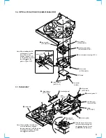
3-6. OPTICAL PICK-UP BLOCK (KHM-230AAA/J1NP)
3
two screws
(PTPWH M2.6)
3
two screws
(PTPWH M2.6)
4
optical pick-up block
(KHM-230AAA/J1NP)
5
four compression springs (932)
2
1
two screws
(PTPWH M2.6)
BU section
Note: When installing the BU
on the chassis, set the
lever (lifter) in free
position, the gear (U/D)
in UP position, and insert
the shaft into the
groove of gear (U/D).
gear (U/D)
b
b
6
connector
(CN002)
7
three screws
(BVTP3
×
8)
8
RF board
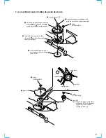
3-7. TABLE ASSY
Note: When installing the table assy
on the chassis assy, engage
the gear (loading C) with the groove
by looking into the gear through
a hole in the table assy.
qa
table assy
9
three screws
(BTTP M2.6)
e
c
c
d
d
e
0
bracket (guide)
gear
(loading C)
7
two screws
(BTTP M2.6)
5
screw
(BTTP M2.6)
6
bracket (guide)
2
two screws
(BTTP M2.6)
1
Slide the tray until the screw
that fixes the bracket (guide)
can be seen through a round
hole , in the table assy.
3
8
bracket (guide 2)
4
wire (flat type)
(6 core) (CN15)
Summary of Contents for SCD-C333ES - Super Audio Cd Changer
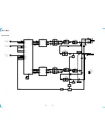
Page 18: ...SCD C333ES 18 18 4 2 SCHEMATIC DIAGRAM RF SECTION Refer to page 40 for Waveforms ...
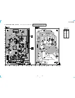
Page 28: ...SCD C333ES 28 28 4 12 SCHEMATIC DIAGRAM AUDIO SECTION 2 3 ...
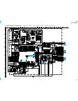
Page 29: ...SCD C333ES 29 29 4 13 SCHEMATIC DIAGRAM AUDIO SECTION 3 3 ...
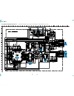
Page 34: ...SCD C333ES 34 34 4 18 SCHEMATIC DIAGRAM HP SECTION ...
Page 36: ...SCD C333ES 36 36 4 20 SCHEMATIC DIAGRAM SENSOR SECTION Refer to page 45 for IC Block Diagram ...
Page 38: ...SCD C333ES 38 38 4 22 SCHEMATIC DIAGRAM POWER SECTION ...


