


2
PRS-500
TABLE OF CONTENTS
1.
SERVICING NOTE
..................................................
3
2.
GENERAL
...................................................................
5
3.
DISASSEMBLY
3-1.
Disassembly Flow ...........................................................
6
3-2.
Soft Cover ........................................................................
7
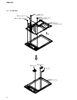
3-3.
B Case Assy .....................................................................
7
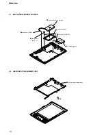
3-4.
A Case Assy .....................................................................
8
3-5.
Magnet .............................................................................
9
3-6.
MAIN Board ....................................................................
9
3-7.
MS FLEXIBLE Board, Chassis ...................................... 10
3-8.
Ink Indicator Element Assy ............................................. 10
4.
TEST MODE
............................................................... 11
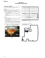
5.
ELECTRICAL ADJUSTMENT
............................. 12
6.
DIAGRAMS
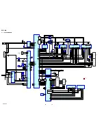
6-1.
Block Diagram ................................................................ 14
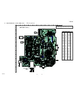
6-2.
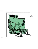
Printed Wiring Boards
– MAIN, DC Board (Side A) – ........................................ 15
6-3.
Printed Wiring Boards
– MAIN, DC Board (Side B) – ........................................ 16
6-4.
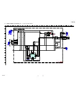
Schematic Diagram – MAIN Board (1/10) – ................. 17
6-5.
Schematic Diagram – MAIN Board (2/10) – ................. 18
6-6.
Schematic Diagram – MAIN Board (3/10) – ................. 19
6-7.
Schematic Diagram – MAIN Board (4/10) – ................. 20
6-8.
Schematic Diagram – MAIN Board (5/10) – ................. 21
6-9.
Schematic Diagram – MAIN Board (6/10) – ................. 22
6-10. Schematic Diagram – MAIN Board (7/10) – ................. 23
6-11. Schematic Diagram – MAIN Board (8/10) – ................. 24
6-12. Schematic Diagram – MAIN Board (9/10) – ................. 25
6-13. Schematic Diagram
– MAIN Board (10/10), DC Board – .............................. 26
7.
EXPLODED VIEWS
7-1.
Overall Assy Section ....................................................... 50
7-2.
A Case Assy Section ........................................................ 51
8.
ELECTRICAL PARTS LIST
.................................. 52
UNLEADED SOLDER
Boards requiring use of unleaded solder are printed with the lead-
free mark (LF) indicating the solder contains no lead.
(Caution: Some printed circuit boards may not come printed with
the lead free mark due to their particular size)
: LEAD FREE MARK
Unleaded solder has the following characteristics.
•
Unleaded solder melts at a temperature about 40
°
C higher
than ordinary solder.
Ordinary soldering irons can be used but the iron tip has to be
applied to the solder joint for a slightly longer time.
Soldering irons using a temperature regulator should be set to
about 350
°
C.
Caution: The printed pattern (copper foil) may peel away if
the heated tip is applied for too long, so be careful!
•
Strong viscosity
Unleaded solder is more viscou-s (sticky, less prone to flow)
than ordinary solder so use caution not to let solder bridges
occur such as on IC pins, etc.
•
Usable with ordinary solder
It is best to use only unleaded solder but unleaded solder may
also be added to ordinary solder.
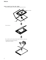
Flexible Circuit Board Repairing
•
Keep the temperature of the soldering iron around 270
°
C
during repairing.
•
Do not touch the soldering iron on the same conductor of the
circuit board (within 3 times).
•
Be careful not to apply force on the conductor when soldering
or unsoldering.
Notes on chip component replacement
•
Never reuse a disconnected chip component.
•
Notice that the minus side of a tantalum capacitor may be
damaged by heat.
• Microsoft, Windows, Windows NT and Windows Media are trademarks or
registered trademarks of Microsoft Corporation in the United States and/or
other countries.
• Adobe and Adobe Reader are trademarks or registered trademarks of Adobe
Systems Incorporated in the United States and/or other countries.
• MPEG Layer-3 audio coding technology and patents licensed from
Fraunhofer IIS and Thomson.
CAUTION
Danger of explosion if battery is incorrectly replaced. Replace
only with the same or equivalent type.


