– 42 –
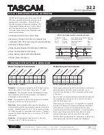
Pin No.
Pin Name
I/O
Pin Description
48
+3.3V
—
Power supply terminal (+3.3V)
49
SNG/CHG
—
Not used (fixed at “L”)
50, 51
JOG1, JOG0
I
JOG dial pulse input Not used (fixed at “L”)
52
SDA
I/O
Two-way data bus with the EEPROM (IC171)
53
SCL
O
Clock signal output to the EEPROM (IC171)
54
2M/4M
I
Select whether D-RAM capacitance 2M bit or 4M bit “L”: 4M bit (external D-RAM), “H”:
2M bit (internal D-RAM of IC121 CXD2654R) (fixed at “H” in this set)
55, 56
NC
—
Not used (fixed at “L”)
57
RXD (UART)
I
UART communication data input from the system controller (IC401)
58
TXD (UART)
O
UART communication data output to the system controller (IC401)
59
RTS
I
RTS (Request To Send) input from the system controller (IC401)
60
CTS
O
CTS (Clear To Send) output to the system controller (IC401)
61, 62
AUBIT0, AUBIT1
—
Not used (fixed at “L”)
63, 64
CLKSET0,
I
Clock destination setting terminal (fixed at “L”)
CLKSET1
65
GND
—
Ground terminal
66
+3.3V
—
Power supply terminal (+3.3V)
67
SCLK
O
Serial clock signal output to the CXD2654R (IC121)
68
SWDT
O
Writing data output to the CXD2654R (IC121)
69
SRDT
I
Reading data input from the CXD2654R (IC121)
70
EMP
O
Emphasis control signal output to the A/D, D/A converter (IC603) when recording mode
71
SCK1
O
Display serial clock signal output terminal Not used (open)
72
SOUT1
O
Display serial data output terminal Not used (open)
73
SIN1
O
Chip select signal output for the display Not used (open)
74
CSB
I
Not used (fixed at “H”)
75
LDON
O
Laser diode on/off control signal output to the automatic power control circuit “H”: laser on
76
PIT/GRV
O
Pit/groove detection signal output terminal
“H”: is output for the playback only disc or TOC area Not used (open)
77
FOK
I
Focus OK signal input from the CXD2654R (IC121)
“H” is input when focus is on (“L”: NG)
78
NC
—
Not used (open)
79
LOCK
O
Lock signal output terminal Not used (open)
80
WRPWR
O
Laser power select signal output to the CXD2654R (IC121) and HF module switch circuit
“L”: playback mode, “H”: recording mode
81
DIG-RST
O
Reset signal output to the CXD2654R (IC121) and BH6511FS (IC152) “L”: reset
82
NC
—
Not used (open)
83
DA-RST
O
Reset signal output to the A/D, D/A converter (IC603) “L”: reset
84
DSEL-A
—
Not used (open)
85
DSEL-B
—
Not used (open)
Laser modulation select signal output to the HF module switch circuit
Stop: “L”, Playback power: “H”,
Recording power:
86
MOD
O
0.5 sec
2 sec
Summary of Contents for MINIDISC ZS-M35
Page 102: ... 130 ZS M35 MEMO ...