23
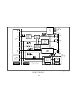
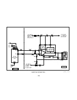
+135 OCP and H Protect
Overview
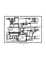
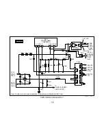
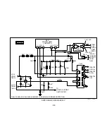
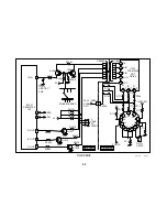
The +135 OCP and H Protect detection circuits output a HIGH to indicate
a problem. These HIGHS are input to the latch circuit that then places a
LOW at the base of the relay drive transistor. This eliminates the current
path necessary to keep the unit ON. When there is a failure, a signal is
also sent to IC1001, which will indicate these failures by flashing the
Standby/Timer LED in sequences of two.
Latch and Hold Down
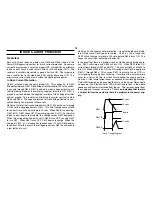
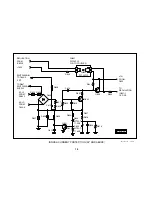
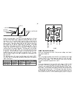
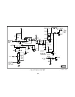
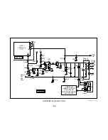
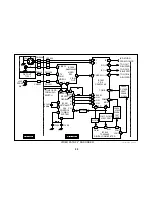
The latch is activated whenever a condition in the +135 volt OCP or the H
Protect circuits causes Q506/B to go HIGH. A HIGH on Q506/B turns it
ON, causing it to turn ON Q507. This drops the drive voltage to Relay
Drive Q607/B, turning it OFF. This in turn removes the ground return path
for RY602 and the unit shuts OFF. During shutdown, the voltage from the
Standby 7.5-volt line maintains the latch. You can determine which of the
two circuits is activating the latch by checking the voltage at D520/A with
a peak hold meter. If that voltage shows a peak near 5 volts, there is a
problem with the OCP.
The LOW signal created by the latch is also applied to the HLDWN line
through R508. The HLDWN line is connected to IC1001 at pin 35. When-
ever this line goes LOW, the Self-Diagnostics are activated and the
Standby/Timer LED flashes in sequences of two.
H Protect
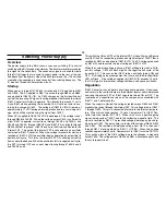
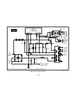
When the horizontal circuit is operating normally, a signal is output from
T505/7 that is also used to supply voltage for the –15 volt line. This signal
is sent through R548 and D519 and is used to maintain the charge of
C546. The DC voltage created by the charge of C546 is input to IC501/5
Non inverting input through R563. This voltage is compared to a refer-
ence voltage of 10.4 volts that is derived by a voltage divider consisting of
R561, D517 and D518. D517 is used for temperature compensation. As
long as IC501/6 is greater than IC501/5, the horizontal circuit is operating
normally. The voltage at IC501/6 is proportional to the High Voltage. If
the High Voltage becomes excessive, the voltage at IC501/5 will become
greater than that at IC501/6. This would cause IC501/7 to output a HIGH.
This HIGH voltage activates the Latch
. Note: This is a departure from
the way previous models have worked. Typically when the H pro-
tect circuit was activated, it turned ON a transistor that grounded
the HP input to the YCJ. In turn, the YCJ would disable HD.
+135 Volt OCP
Over current is detected by monitoring the voltage across R556 and R553.
When this voltage, which rises as more current is drawn, gets to a level
that causes Q505 to turn ON, the latch will be activated. C534 prevents
premature triggering of OCP.
Three main components generally cause this type of failure. They are
T505 FBT, Q502 H Out and the CRT Drive (not shown). You should check
Q502 with an ohmmeter first. This component usually fails with a C-E
short. Unloading each of them from the circuit one at a time can eliminate
these components.
Note: Before doing this, ensure that SW501 H
Centering Switch is in the center position. Damage will occur to the
set if it is not.
•
Unplug the unit. Start with the easiest by unplugging CN502 from the
A board and reapplying power. If the symptom changes from se-
quences of two flashes to sequences of five flashes, replace IC702
CRT Drive on the C board.
•
If the symptom remains, unplug the set, reconnect CN502 and re-
move Q502. Re-apply power. If the symptom changes from sequences
of two flashes to sequences of four flashes, replace Q502.
•
If the symptom remains, unplug the set and remove L510 and R568.
These points were chosen because they do not have eyelets. Conse-
quently they are easier to remove compared to unsoldering T505/2.
This eliminates the T505 FBT. If the symptom changes from sequences
of two flashes to sequences of four flashes, replace T505.
In very rare cases the protection transistor, Q505 in this case, has be-
come leaky. This can generally be determined by checking the transistor
with an ohmmeter or diode checker. It is also possible that IC501 has
become faulty.
Summary of Contents for FD TRINITRON WEGA KV-13FM12
Page 27: ...22 NOTES ...
Page 48: ...APPENDIX ...

