29
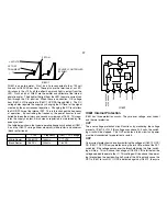
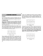
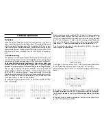
IC502/1 1V 5MS
IC502/7 1V 5MS
IC502/3 20V 5MS
IC502/5 20V 5MS
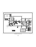
Vertical Deflection
Overview
Since the Vertical Deflection circuitry has changed little in the last few
years, we will not discuss its circuit description. This section of the course
will be used to offer troubleshooting tips for repairing BA-5 chassis sets.
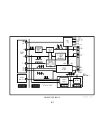
If the vertical section is defective, there will be pulses missing on the I
protect line to Syscon. If these pulses are missing, Syscon will shut OFF
the power relay and the Standby/Timer LED will flash in sequences of
four.
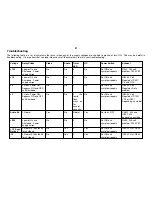
Troubleshooting
The following is a troubleshooting procedure for the vertical section if you
are sure that the sequence of four flashing lights is not caused by a direct
short on one of the power supply lines or a horizontal circuit malfunction.
Remember that the chirping transformer in the power supply may
indicate a direct short on a power supply line or a power supply
problem, and no horizontal is characterized by lack of High Voltage.
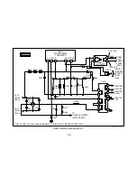
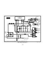
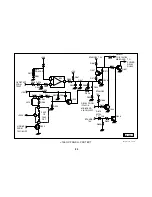
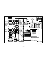
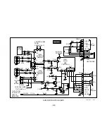
The first step in checking the Vertical deflection circuit is to check the
supply voltages at IC502/2 and IC502/4. If these voltages are missing,
R549 and R550 should be checked. These resistors are .47 ohms and
should always be checked with an ohmmeter because they have a ten-
dency to change value when subjected to heat. They should never read
much higher than .47 ohms with an ohmmeter.
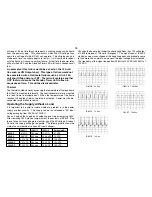
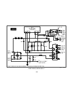
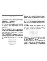
Next check the signals at IC502/1 and 7. They should look like the wave-
forms shown below.
If these signals are missing, check IC1301/13 and 14. If these signals are
not present, check the data and clock lines at IC1301/34 and 35. The
YCJ will not output vertical drive unless communication is okay between
the YCJ and the Syscon. If data or clock is missing, unload these lines
from each IC individually. When a lead is lifted and the signal returns,
replace that IC. If communication appears normal, replace the YCJ.
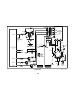
If the drive signals are present, check the signal at IC502/3. This signal
should appear as shown below.
If this signal is missing, replace IC502. If the signal appears distorted or
is missing the retrace portion, check or replace C541 and D510.
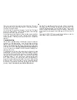
Check the output from IC502/5. It should look like the waveform shown
below.
If the signal at IC502/5 is missing, replace IC502. Check to be sure that
the signal is getting from IC502/3 to the I protect input on the Syscon.
The Syscon is located on the MA or MB board depending on the size of
the set.
In the case of size or centering problems, check the values of input resis-
tors R517, R518, R519 and R540.
Summary of Contents for FD TRINITRON WEGA KV-13FM12
Page 27: ...22 NOTES ...
Page 48: ...APPENDIX ...

