33
RGB Drive
Overview
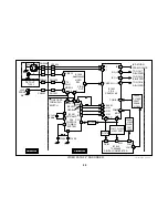
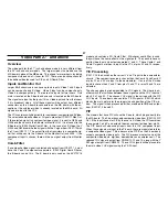
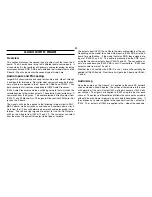
This section describes how the RGB signals are displayed by the picture
tube. In addition, we will discuss the IK/AKB circuit and how it functions in
the BA-5 chassis. Troubleshooting no video problems by using the IK
pulses output by the YCJ will also be covered.
IK Pulses and Video Blanking
When the set is turned ON and communication is established between
the YCJ and Syscon, IK pulses are output for each color. These pulses
are one horizontal line in duration and they occur during every field. They
are output so they occur on consecutive lines with red first, followed by
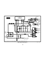
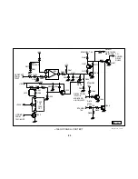
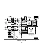
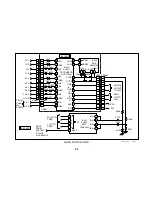
green and blue. They are buffered by Q1315, Q1316 and Q1317, and
applied to CN1303.
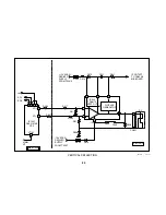
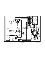
CN1303 is connected to CN705 on the CB board. The cable connecting
the two boards is hardwired and cannot be unplugged from either end.
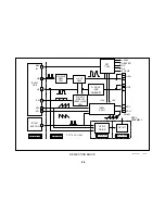
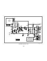
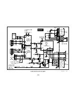
The RGB signals that are applied to the CB board are input directly into
pins 1, 2 and 3 of IC702 CRT Drive. IC702 amplifies and inverts these
signals, and applies them to the cathode of the tube for their respective
colors. If the tube is biased correctly, three lines will be produced in the
overscan area of the picture tube.
IC702/5 IK outputs a voltage signal that represents the amount of total
current being drawn by the tube cathodes. Since each color is outputting
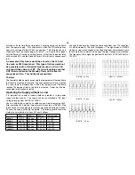
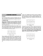
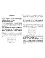
a pulse for one H line, in every field we would see a waveform like that
shown below at Q1350 or Q1331 Base. It is very hard to see this wave-
form at other places so it is recommended that you only check IK return
here.
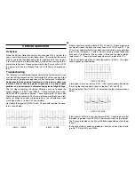
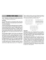
Q1331/B 1v 5ms
Place your scope in delayed mode and highlight the area that appears to
be one pulse. Expand it and you will see that there are three distinct
pulses, one for each color. Your scope should be set to 5ms per division.
Some scopes that have less than 100MHz bandwidth may have trouble
triggering on these signals.
Once the IK detect circuit in the YCJ detects that the proper current is
flowing to each cathode, the video is unblanked and a picture may be
seen. The YCJ continues to monitor the IK IN line for the proper signal
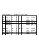
levels. If there is a failure during operation, the Standby/Timer LED will
flash in sequences of five.
Tube Bias
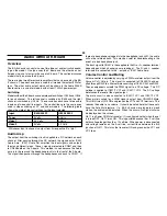
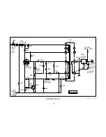
The CRT requires high voltage and other biasing voltages to properly
display a picture. First it requires a heater voltage, which is developed by
the FBT (not shown) on the A board. The heater is necessary to heat the
cathode so that it can emit electrons. If it is missing, the cathode will not
emit electrons and consequently there would be no picture. The wave-
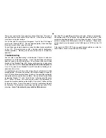
form below shows the signal at CRT pin 7 H1.
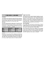
CRT Socket/7 20v 10us
The G1 input on the tube is a control grid. There are three separate pins
on the tube for G1. They are pins 6, 9 and 13. These pins are connected
together and tied to ground through R715. There is approximately -.01
volts present at these pins when no video is input.
G2 is also a control grid and is used to limit the acceleration of electrons
as they travel through the neck of the tube. These changes in the accel-
eration of the beam change the picture brightness. G2 measures about
316 volts on a 20” inch sample. This voltage will increase as screen size
increases. G2 is set by inputting a gray scale pattern and adjusting the
G2 VR on the FBT (not shown) so that the darkest bar is completely
black. This is done with Contrast set to max and Brightness set to the
midpoint.
Summary of Contents for FD TRINITRON WEGA KV-13FM12
Page 27: ...22 NOTES ...
Page 48: ...APPENDIX ...

