27
Horizontal Deflection
Overview
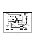
Since the Horizontal Deflection circuitry has changed little in the last few
years, we will not discuss its circuit description. This section of the course
will be used to offer troubleshooting tips for repairing BA-5 chassis sets.
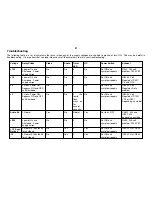
Troubleshooting
The following is a procedure to try if the set is shutting down with a
four
flashing sequence indication from the Self-diagnostics and No High
Voltage
presen
t. The presence of High Voltage for even a short time is
an indication that the Horizontal circuit is functioning normally and your
problem lies in the vertical section. Keep in mind the scan supplies are
part of the Horizontal circuit.
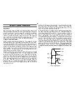
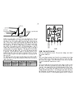
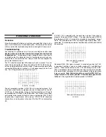
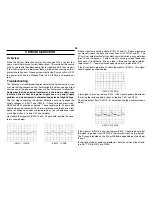
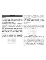
The YCJ should always output HD whenever 9 volts is present. You can
check this by turning the set ON and checking IC1301/19 HD for the sig-
nal shown below before the set shuts down. Another method would be to
remove the MB board and connect a +9 volt power supply to the 9-volt
line. The HD signal should be output from pin 19.
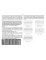
IC1301/19 2V 20US
The only exception would be if IC1301/18 HP is shorted to ground. This
pin serves a dual function in previous chassis. In those sets it is the HP/
H OFF line. In these models, during an H protect condition, pin 18 would
be grounded and HD at pin 19 would be halted. The H protect circuit does
not operate in this manner in the BA-5 chassis, but should IC1301/18 HP
be grounded, it would cause HD to cease. IC1301/18 HP should be
checked for a short to ground in the event that the YCJ is not outputting
HD.
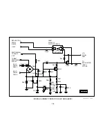
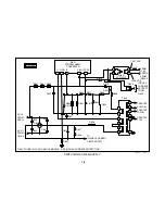
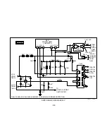
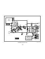
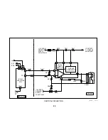
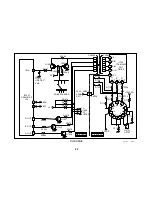
If IC1301 YCJ is outputting HD, the next step is to see if this signal is
present at the base of Q501 H Drive. If the signal looks good at Q501/B
then the base of Q502 H Out could be unloaded by unsoldering 1 side of
R504. This will determine if Q501 can output a signal with its load, T501,
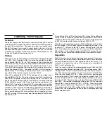
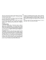
connected. The following waveform should be seen at R504 with Q502/B
disconnected.
R504 with Q502/B unsoldered
5V 20US
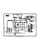
Reconnect R504 if this signal is present. In order to be certain that T501
is capable of handling a load, you should unsolder L510 and R648 (not
shown). These components pass the +135 volts through to T505 FBT.
These components were chosen because they are easier to unsolder
then more evident components, which are soldered to the board where
there are eyelets.
Note: Before doing this, ensure that SW501 H Cen-
tering Switch is in the center position. Otherwise damage will occur
to the set.
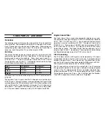
The signal below should be present at Q502/B.
R504 with Q502/6 unsoldered
5V 20US
Summary of Contents for FD TRINITRON WEGA KV-13FM12
Page 27: ...22 NOTES ...
Page 48: ...APPENDIX ...

