24
DVP-CX995V
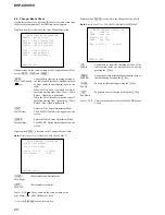
1-3. DVD Dual Layer Disc (Parallel)
Select
[3]
, insert DVD dual layer disc, and press
[ENTER]
key, and
the adjustment will be made through the following steps, then
adjusted values will be written to the flash memory. The disc slot
No. 3 is used in the changer type model. If there is no disc on the
disc slot No. 3, the tray will be open to wait for closing. If there is a
disc on the table, the adjustment starts immediately. If you put a
disc prior to adjustment, confirm that the DL disc is set on the disc
slot 3. Also, when the adjustment is completed, the result of the
each setting value is displayed as follows.
DVD Dual Layer Disc Adjustment Steps
1. Sled Reset
2. Set Disc Type DL
3. Laser Diode (DVD) ON
4. Focus Error Check
5. Focus ON
6. Spindle Start
7. Tracking Error Level Adjust
8. Tracking Error Offset Adjust
9. Tracking ON
10. RF Level Adjustment
11. Spindle Calibration
12. Tracking Off
13. Tracking Error Level Adjust 2nd
14. Tracking Error Offset Adjust 2nd
15. Tracking ON
16. Auto Focus Gain Adjust L0
17. Auto Tacking Gain Adjust L0
18. Sled ON
19. CLV ON
1-1. DVD Single Layer Disc
Select
[1]
, insert DVD single layer disc, and press
[ENTER]
key,
and the adjustment will be made through the following steps, then
adjusted values will be written to the flash memory. The disc slot
No. 1 is used in the changer type model. If there is no disc on the
disc slot No. 1, the tray will be open to wait for closing. If there is a
disc on the table, the adjustment starts immediately. If you put a
disc prior to adjustment, confirm that the SL disc is set on the disc
slot 1. Also, when the adjustment is completed, the result of the
each setting value is displayed as follows.
DVD Single Layer Disc Adjustment Steps
1. Sled Reset
2. Set Disc Type SL
3. Laser Diode (DVD) ON
4. Focus Error Check
5. Focus ON
6. Spindle Start
7. Tracking Error Level Adjust
8. Tracking Error Offset Adjust
9. Tracking ON
10. RF Level Adjustment
11. Spindle Calibration
12. Tracking Off
13. Tracking Error Level Adjust 2nd
14. Tracking Error Offset Adjust 2nd
15. Tracking ON
16. Auto Focus Gain Adjust L0
17. Auto Tracking Gain Adjust L0
18. Sled ON
19. CLV ON
20. Auto Focus Balance Adjust L0
21. Auto RFEQ Boost Adjust L0
22. Jitter measure
23. Search Check
24. All Servo Off
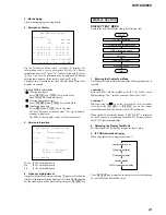
Result Display
Result
disc type : SL
An.Off.AB xx xx TE levDVD xx
An.Off.CD xx xx TE levCD --
An.Off.EF -- -- TE Offset xx
An.G.Main xx FCS Gain xx
An.G.Side -- TRK Gain xx
RF level xx FCS Bal. -- xx
FE S L0,1 xx -- REFQ -- xx
VTS2 xx Jitter xx
Exit:RETURN
1-2. CD Disc
Select
[2]
, insert CD disc, and press
[ENTER]
key, and the adjustment
will be made through the following steps, then adjusted values will
be written to the flash memory. The disc slot No. 2 is used in the
changer type model. If there is no disc on the disc slot No. 2, the
tray will be open to wait for closing. If there is a disc on the table,
the adjustment starts immediately. If you put a disc prior to
adjustment, confirm that the CD is set on the disc slot 2. Also, when
the adjustment is completed, the result of the each setting value is
displayed as follows.
CD Adjustment Steps
1. Sled Reset
2. Set Disc Type CD
3. Laser Diode (CD) ON
4. Focus Error Check
5. Focus ON
6. Spindle Start
7. Tracking Error Level Adjust
8. Tracking Error Offset Adjust
9. Tracking ON
10. RF Level Adjustment
11. Spindle Calibration
12. Auto Focus Gain Adjust
13. Auto Tracking Gain Adjust
14. Sled ON
15. CLV ON
16. Auto Focus Balance Adjust
17. Auto RFEQ Boost Adjust
18. Jitter measure
19. Search Check
20. All Servo Off
Result Display
Result
disc type : CD
An.Off.AB xx xx TE levDVD --
An.Off.CD xx xx TE levCD xx
An.Off.EF xx xx TE Offset xx
An.G.Main xx FCS Gain xx
An.G.Side xx TRK Gain xx
RF level xx FCS Bal. -- xx
FE S L0,1 xx -- REFQ -- xx
VTS2 -- Jitter xx
Exit:RETURN


