86
DVP-CX995V
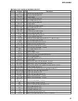
Pin No.
Pin Name
I/O
Description
63
H_SEL1
I
Host selection signal input terminal Fixed at "H" in this set
64 to 68
D_ADDR1 to
D_ADDR5
O
Address signal output to the SD-RAM
69
GND_IO3
-
Ground terminal
70 to 75
D_ADDR0,
D_ADDR6 to
D_ADDR8,
D_ADDR10,
D_ADDR13
O
Address signal output to the SD-RAM
76
VCC_IO3
-
Power supply terminal (+3.3V)
77 to 79
D_ADDR9,
D_ADDR11,
D_ADDR12
O
Address signal output to the SD-RAM
80
D_WEN
O
Write enable signal output to the SD-RAM
81
D_RASN
O
Row address signal output to the SD-RAM
82
D_CASN
O
Column address signal output to the SD-RAM
83
GND_IO4
-
Ground terminal
84
GND_CORE2
-
Ground terminal
85
VCC_CORE2
-
Power supply terminal (+1.8V)
86
D_CLK
O
Clock signal output to the SD-RAM
87
D_DQ5
I/O
Two-way data bus with the SD-RAM
88
D_UDQM
O
Write mask signal output to the SD-RAM (upper byte)
89
D_LDQM
O
Write mask signal output to the SD-RAM (lower byte)
90, 91
D_DQ7, D_DQ8
I/O
Two-way data bus with the SD-RAM
92
VCC_IO4
-
Power supply terminal (+3.3V)
93 to 98
D_DQ4, D_DQ6,
D_DQ9 to D_DQ11
I/O
Two-way data bus with the SD-RAM
99
GND_IO5
-
Ground terminal
100 to 105
D_DQ0 to D_DQ2,
D_DQ12 to D_DQ14
I/O
Two-way data bus with the SD-RAM
106
VCC_IO5
-
Power supply terminal (+3.3V)
107
D_DQ15
I/O
Two-way data bus with the SD-RAM
108
DSD_PCM_0
O
DSD data (for front L-ch) output to the D/A converter
109
DSD_PCM_1
O
DSD data (for front R-ch) output to the D/A converter
110
DSD_PCM_2
O
DSD data (for center) output to the D/A converter
111
DSD_PCM_3
O
DSD data (for woofer) output to the D/A converter
112
GND_IO5
-
Ground terminal
113
DSD_PCM_4
O
DSD data (for rear L-ch) output to the D/A converter
114
DSD_PCM_5
O
DSD data (for rear R-ch) output to the D/A converter
115, 116
DSD_PCM_6,
DSD_PCM_7
O
DSD data output terminal Not used
117
DSD_PCM_8
O
DSD clock signal output to the D/A converter
118
VCC_IO6
-
Power supply terminal (+3.3V)
119
DSD_PCM_10
O
DSD data output terminal Not used
120
DSD_PCM_9
O
DSD data (for R-ch) output to the D/A converter
121
DSD_PCM_11
O
DSD data (for L-ch) output to the D/A converter
122
RESETN
I
Reset signal input from the CPU "L": reset
123
H_A_SEL
I
Address signal input from the CPU
124 to 128
H_A6 to H_A2
I
Address signal input from the CPU

