– 27 –
Editing
51
Changing the recorded still
image size (RESIZE)
1
Set the MODE selector to
PLAY and display the image
to resize.
2
Select [TOOL] and then
[RESIZE] from the menu.
3
Select the desired image
size.
DSC-S50
1600
×
1200, 1024
×
768, 640
×
480
DSC-S30
1472
×
1104, 1280
×
960,
1024
×
768, 640
×
480
The changed image is recorded,
then the display returns to the
image display before resizing.
To return to the original size
Select [CANCEL] in step
3
.
Notes
•
You cannot change the size of images
recorded in TEXT mode or uncompressed
images.
•
When you change from a small size to a
large size, the picture quality deteriorates.
•
The original image is retained even after
resizing.
•
The resized image is recorded as the
newest file.
1,2,3
1
Copying images (COPY)
You can copy images to another
“Memory Stick.”
1
Set the MODE selector to
PLAY, then display the image
to copy.
2
Select [TOOL], [COPY], and
then [OK] from the menu.
“FILE ACCESS” appears.
3
When “CHANGE MEMORY
STICK” appears, eject the
“Memory Stick.”
“INSERT MEMORY STICK”
appears.
4
Insert the “Memory Stick” on
which to copy the image.
“RECORDING” appears. When
copying is completed,
“COMPLETE” appears.
If you exchange the “Memory
Stick,” the same image is copied
again.
After copying is finished
Select [EXIT].
If you do not select [EXIT], the same
image is copied each time you
exchange the “Memory Stick.”
In single mode
1,2
1
B
52
1
Set the MODE selector to
PLAY, then display the INDEX
screen.
2
Select [TOOL], [COPY], and
then [SELECT] from the
menu.
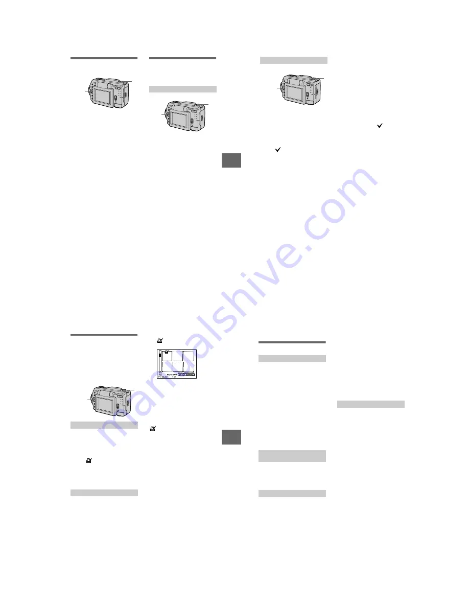
3
Select the image to copy.
The
(select) indicator appears
on the image.
4
Select [ENTER].
“MEMORY STICK ACCESS”
appears.
5
When “CHANGE MEMORY
STICK” is displayed, eject the
“Memory Stick.”
“INSERT MEMORY STICK”
appears.
6
Insert another “Memory
Stick.”
“RECORDING” appears. When
copying is completed,
“COMPLETE” appears.
If you exchange the “Memory
Stick,” the same image is copied
again.
In INDEX mode
1,2,3,4
1
After copying is finished
Select [EXIT].
If you do not select [EXIT], the same
image is copied each time you
exchange the “Memory Stick.”
To cancel copying part-way
Change the MODE selector setting or
turn off the power.
Notes
•
You cannot copy uncompressed images.
•
You cannot copy images that are bigger
than 1.4 MB at once. If “NOT ENOUGH
MEMORY” appears or
flashes on the
INDEX screen, cancel some images to
copy and try again.
Editing
53
Selecting still images to print
(PRINT MARK)
You can mark a print mark on still
images recorded with your camera.
This mark is convenient when you
have images printed at a shop that
conforms with the DPOF (Digital Print
Order Format) standard.
1
Set the MODE selector to
PLAY and display the image
you want to print.
2
Select [FILE], [PRINT MARK],
and then [ON] from the menu.
The
(print)
mark
is
displayed
on the image.
To unmark the print mark
Select [OFF] in step
2
.
1
Set the MODE selector to
PLAY, then display the INDEX
screen.
2
Select [FILE], [PRINT MARK],
and then [SELECT] from the
menu.
3
Select the images to mark
with the control button.
In single mode
In INDEX mode
1,2,3,4
1
4
Select [ENTER].
of the selected images change
from green to white.
To unmark selected print marks
Select the images to unmark in step
3
with the control button, then select
[ENTER].
To unmark all the print marks
Select [FILE], [PRINT MARK],
[ALL] and then [OFF] from the menu.
of all images are unmarked.
Notes
•
You cannot mark moving images or
images recorded in TEXT mode.
•
If you mark an image recorded in TIFF
mode with a print mark, only the
uncompressed image is printed, and the
JPEG image recorded at the same time is
not printed.
B
54
Additional information
Precautions
Cleaning the LCD screen
Wipe the screen surface with a cleaning
cloth (not supplied) or a LCD cleaning kit
(not supplied) to remove fingerprints, dust,
etc.
Cleaning the camera surface
Clean the camera surface with a soft cloth
slightly moistened with water, then wipe the
surface dry. Do not use any type of solvent
such as thinner, alcohol or benzene as this
may damage the finish or the casing.
After using your camera at the
seashore or other dusty locations
Clean your camera carefully. Otherwise, the
salty air may corrode the metal fittings or
dust may enter the inside of your camera,
causing a malfunction.
Your camera is designed for use between the
temperatures of 32˚F and 104˚F (0˚C and
40˚C). Recording in extremely cold or hot
places that exceed this range is not
recommended.
If the camera is brought directly from a cold
to a warm location, or is placed in a very
damp room, moisture may condense inside
or outside the camera. Should this occur, the
camera will not operate properly.
Moisture condensation occurs
easily when:
•
The camera is brought from a cold location
such as a ski slope into a warmly heated
room.
•
The camera is taken from an air-
conditioned room or car interior to the hot
outdoors, etc.
How to prevent moisture
condensation
When bringing the camera from a cold place
to a warm place, seal the camera in a plastic
bag and allow it to adapt to conditions at the
new location over a period of time (about an
hour).
If moisture condensation occurs
Turn off the camera and wait about an hour
for the moisture to evaporate. Note that if
you attempt to record with moisture
remaining inside the lens, you will be
unable to record clear images.
•
Unplug the unit from the wall outlet
(mains) when you are not using the unit for
a long time.
•
To disconnect the power cord (mains lead),
pull it out by the plug. Never pull the
power cord (mains lead) itself.
•
Do not operate the unit with a damaged
cord or if the unit has been dropped or
damaged.
•
Do not bend the power cord (mains lead)
forcibly, or place a heavy object on it. This
will damage the cord and may cause fire or
electrical shock.
•
Prevent metallic objects from coming into
contact with the metal parts of the
connecting section. If this happens, a short
may occur and the unit may be damaged.
•
Always keep metal contacts clean.
•
Do not disassemble the unit.
•
Do not apply mechanical shock or drop the
unit.
•
While the unit is in use, particularly during
charging, keep it away from AM receivers
and video equipment. AM reception and
video operation are disturbed.
•
The unit becomes warm during use. This is
not a malfunction.
•
Do not place the unit in locations that are:
— Extremely hot or cold
— Dusty or dirty
— Very humid
— Vibrating
On cleaning
Note on operating
temperature
On moisture condensation
On AC power adaptor