


5-34
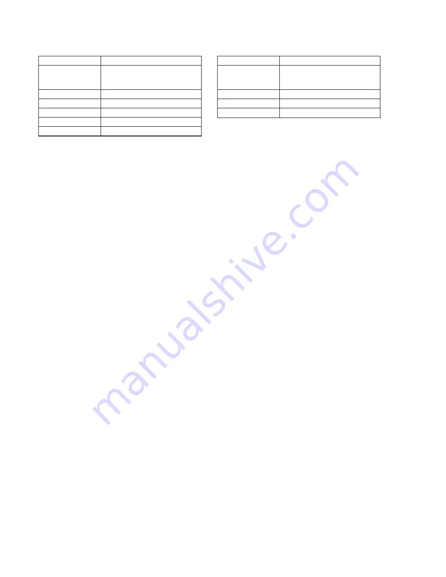
19. CCD White Defect Compensation
Mode
STILL
Subject
Clear chart
(25 cm from the front of the lens)
(Note1)
Measurement Point
Display data of page: 6, address: 55
Measuring Instrument
Adjustment remote commander
Adjustment Page
7
Adjustment Address
88 to A3
Specified value
Data
<
7F: OK, Data
>
80: NG
Note 1:
Check that there are no dust, no dirt and no reflection on the clear
chart.
Note 2:
Any subject other than the clear chart should not be in the screen.
Adjusting method:
1)
Select page: 0, address: 01, and set data: 01.
2)
Select page: 5, address: F1, and set data: FF.
3)
Select page: F, address: DE, after noting down the data, set
data: 14, and press the PAUSE button of the adjustment remote
commander.
4)
Select page: F, address: E3, after noting down the data, set data:
28, and press the PAUSE button.
5)
Select page: 6, address: 01, set data: 8B, and press the PAUSE
button.
(The CCD white defect compensation is performed and the
adjustment data is stored in page: 7, address: 88 to A3.)
6)
Select page: 6, address: 02, and check that the data changes to
“01”.
7)
Select page: 6, address: 55, and check the data satisfies specified
value.
Processing after Completing Adjustments:
1)
Select page: F, address: DE, set the data noted down at step 3),
and press the PAUSE button.
2)
Select page: F, address: E3, set the data noted down at step 4),
and press the PAUSE button.
3)
Select page: 6, address: 01, and set data: 00, and press the
PAUSE button of the adjustment remote commander.
4)
Select page: 5, address: F1, and set data: 00.
5)
Select page: 0, address: 01, and set data: 00.
20. CCD White Defect Compensation Check
Mode
STILL
Subject
Clear chart
(25 cm from the front of the lens)
(Note1)
Measurement Point
Display data of page: 6, address: 55
Measuring Instrument
Adjustment remote commander
Specified Value
00
Note 1:
Check that there are no dust, no dirt and no reflection on the clear
chart.
Note 2:
Any subject other than the clear chart should not be in the screen.
Note 3:
This adjustment should be carried out upon completion of
“CCD White Defect Compensation”.
Checking method:
1)
Turn the power of the unit OFF and then ON.
2)
Wait until the camera picture appear on the screen.
3)
Select page: 0, address: 01, and set data: 01.
4)
Select page: 5, address: F1, and set data: FF.
5)
Select page: F, address: DE, after noting down the data set data:
0A, and press the PAUSE button.
6)
Select page: F, address: E3, after noting down the data, set data:
80, and press the PAUSE button.
7)
Turn the power of the unit OFF and wait for four seconds.
8)
Turn the power of the unit ON.
9)
Select page: 0, address: 01, and set data: 01.
10) Select page: 6, address: 55, and check that the data is “00”. (If
the data is other than “00”, white defect compensation has
errors.)
11) Select page: F, address: E3, set data: A0, and press the PAUSE
button.
12) Select page: 6, address: 01, set data: 87, and press the PAUSE
button.
13) Select page: 6, address: 02, and check that the data changes to
“01”.
14) Select page: 6, address: 55, and check that the data is “00”. (If
the data is other than “00”, black defect compensation has
errors.)
Processing after Completing Adjustments:
1)
Select page: F, address: DE, set the data noted down at step 5),
and press the PAUSE button.
2)
Select page: F, address: E3, set the data noted down at step 6),
and press the PAUSE button.
3)
Select page: 6, address: 01, and set data: 00, and press the
PAUSE button of the adjustment remote commander.
4)
Select page: 5, address: F1, and set data: 00.
5)
Select page: 0, address: 01, and set data: 00.
Summary of Contents for Cyber-shot DSC-F505
Page 7: ...1 1 DSC F505 SECTION 1 GENERAL This section is extracted from instruction manual ...
Page 8: ...1 2 ...
Page 9: ...1 3 ...
Page 10: ...1 4 ...
Page 11: ...1 5 ...
Page 12: ...1 6 ...
Page 13: ...1 7 ...
Page 14: ...1 8 ...
Page 15: ...1 9 ...
Page 16: ...1 10 ...
Page 17: ...1 11 ...
Page 18: ...1 12 ...
Page 19: ...1 13 ...
Page 20: ...1 14 ...
Page 21: ...1 15E ...


