


2-2
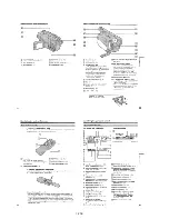
NOTE: Follow the disassembly procedure in the numerical order given.
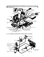
2-1. PD-117 BOARD, BACK LIGHT, LIQUID CRYSTAL DISPLAY PANEL (TRV MODEL)
PD
-117
PD
-117
1
Two screws
(M2
×
4),
lock ace, p2
1
Five claws
6
Four claws
5
Indication LCD
block assembly
8
Back light
7
7
Two tapping screws
(B2
×
7)
2
Two tapping screws
(B2
×
5)
q;
Screw
(M2
×
3)
3
Two claws
5
Three claws
qa
Two claws
8
Two claws
qs
Panel frame (93)
9
P cabinet (M)(93)
assembly
qd
Liquid crystal
indicator module
Liquid crystal
indicator module
qf
Back light
Cold cathode
fluorescent tube
qg
PD-117 board
6
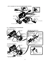
Adjustment
remote commander
(RM-95)
LANC
jack
AC POWER
ADAPTOR
AC IN
Multi CPC jig
(J-6082-311-A)
Back light
Cold cathode
fluorescent tube
PD-117 board
CN5502
[PD-117 BOARD SERVICE POSITION]
4
P cabinet (C)(98)
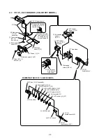
Indication LCD block assembly
(Super night shot model)
3
Remove the
two solderings
4
Remove the
two solderings
2
LCD
holder (93)
1
Four claws
Liquid crystal display panel
2
LCD
holder (98)
3
Liquid crystal
display panel
Liquid crystal display panel
(TRV night shot model)
REMOVING THE BACK LIGHT
REMOVING THE
LIQUID CRYSTAL DISPLAY PANEL
(SUPER NIGHT SHOT MODEL)
(TRV NIGHT SHOT MODEL)
(PRECAUTION DURING INSTALLATION)
FP-155 flexible
board
Summary of Contents for CCD-TRV67 - Video Camera Recorder 8mm
Page 12: ...1 2 ...
Page 13: ...1 3 ...
Page 14: ...1 4 ...
Page 15: ...1 5 ...
Page 16: ...1 6 ...
Page 17: ...1 7 ...
Page 18: ...1 8 ...
Page 19: ...1 9 ...
Page 20: ...1 10 ...
Page 21: ...1 11 ...
Page 22: ...1 12 ...
Page 23: ...1 13 ...
Page 24: ...1 14 ...
Page 25: ...1 15 ...
Page 26: ...1 16 ...
Page 27: ...1 17 ...
Page 28: ...1 18 ...
Page 29: ...1 19 ...
Page 30: ...1 20E ...


